
5K Owner Manual

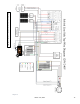


Table Of Contents
- Upon Receiving Shipment
- Spec Sheet
- Wiring Diagrams
- GUI Screens
- Physical Installation
- Inverter Components
- Deciding Backup Circuits
- Single System Installs
- Mounting the Sol-Ark
- Integrating Batteries (Sol-Ark POWERED "OFF")
- E.M.P Systems Only
- Connecting Solar Panels
- Integrating a Generator
- Integrating Sensors and Accessory Placement
- Battery Temperature Sensor
- Limiter Sensors (CT Sensors)
- GEN Start Signal (Two-Wire)
- CANbus & RS485
- Wi-Fi Antenna (Dongle)
- Emergency Stop Signal & PV Rapid Shutdown Signal
- Misc. Hardware Recommendations
- Check the voltage on each PV input circuit
- Check Grid Input Voltage
- Check Battery Voltage
- Provide Power to Sol-Ark
- Indicator LED's
- Power Cycle Sequence
- Wi-Fi / Internet Connection
- Programming Guide
- Limiter Sensors (CT Sensors)
- Install Tips
- Batteries
- Troubleshooting Guide
- LCD is not powering on
- Panels are connected, but DC Light is not on
- Panels are not producing
- Panels are not producing much power
- The system does not keep batteries charged
- Auto Gen-Start not working
- Normal LED isn't on
- The alarm light is on
- Grid HM value is negative when it should be positive (only applies in limited home mode)
- AC Overload Fault or Bus Unbalance Fault
- The system connects to grid and quickly disconnects
- DC Overload Fault
- System is beeping
- Battery cable sparks when connected
- Battery symbol on the home screen is red
- Battery symbol on the home screen is yellow
- Grid symbol on the home screen is yellow
- System has restarted
- Batteries were connected backward
- Why is the LCD screen still on when the power button is off?
- The Batt % meter is not reaching 100%
- Generator setup is reading 0Hz
- Color Touchscreen is Frozen
- Troubleshooting Phasing Issues
- Sol-Ark 5K Error Codes
- Install Verification Checklist
- Sol-Ark 5K Limited Warranty

March 14
th
, 2022 19
Integrating Sensors and Accessory Placement
Battery Temperature Sensor
• Place between batteries with tape (See Fig. C).
• This sensor has no polarity and helps perform voltage charging adjustments
and capacity calculations.
Note: Lithium Batteries do NOT require a Temperature sensor.
Limiter Sensors (CT Sensors)
• Install sensors on incoming electrical service wires on L1 and L2 (see Diagrams Section)
• Limited To Home Mode (meter zero) and Peak Shaving Modes require CT sensors
• To ensure the sensors will fit, please check the wire size before ordering
• See pg. 35 for additional CT sensor information.
GEN Start Signal (Two-Wire)
• The signal comes from a normally open relay that closes when the Gen Start state is active
CANbus & RS485
• To connect batteries to the Sol-Ark 5K via RJ45, you need to splice the end connecting to the Sol-Ark 5K
• Use the middle two conductors
• RS485 is SunSpec draft 4 (will not work with draft 3)
Wi-Fi Antenna (Dongle)
Remote monitoring and software updates require an internet connection through the Wi-Fi dongle
Sensor Pin Out (Located in Sol-Ark user
(1,2) Batt Temp: Battery Temperature Sensor has
no polarity and is needed for voltage correction
when using lead acid batteries.
(+3, -4) CT1 & (+5,-6) CT2: Current transformers
used for limited to home mode and peak shaving
(7,8) Gen Start Relay: Two wire start for
generators, simple open or closed relay
(9,10) Gen On Relay: Not currently used
(B 11, B 12) Emergency Stop: Short these pins to
initiate emergency stop. This will shutdown AC
output from the inverter and initiate rapid
shutdown of the PV.
(+13, -14) Optional 12V input signal for RSD
(+15, -16) 12V power supply for RSD
transmitters: such as TIGO and Midnite
Rated for a maximum of 1.2W (100mA @12V)
Fig. C