
Instructions


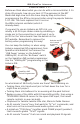

Step 3 - Resistors: First thing to do is to bend the leads right over 90° close
to the resistor body, so they fit into their spot on the PCB. Next, install the
10k resistor (colors: Brown / Black / Orange) to location ‘R1’, and solder it
in.
Don’t mix these up! Your SB-FireFly will still work, but barely!
Step 4 - Decision time! Would you like to keep the SB-Firefly in the
standard blinky configuration, or would you like to use it for other small
microcontroller projects and purposes? This step is where you’ll want to
make your decision.
For the standard Firefly configuration, stay the course; for Digispark
shield compatibility, skip ahead to page 9 for alternate parts installation
Bend these...
...into these!
47ohm
10k
Then install the 10k
resistor into R1
SB-FireFly Manual
Construction!
6
Now install the 47
ohm resistor (colors:
yellow / purple /
black), into to
location ‘R2’.
Step 5 - Trimming! Yes, we have to
specifically tell you to do this. If you don’t
trim the sticky-outy bits on the bottom, the
battery holder will not fit very well.
Trim all pins/leads down, nice and tidy.
Trim all leads & pins
on the PCB underside