
Instructions


Installation of the
male 2x3
programming
header
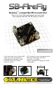
SB-FireFly Manual
Construction!
9
FireFly - Digispark shield compatibility configuration:
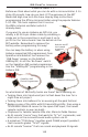
Continue from here if you’d like to use your Firefly for other fun and
devious applications. First install and solder in the headers. The
male 2x3 header is installed over the open hardware logo. The
female 3 pin header goes to the left of the switch and the female 6
pin header is situated to the left of the male 2x3 header.
Installation of the
female Digispark
Compatible
Headers
Install the 0.1uF Capacitor:
This cap prevents unwanted noise
from disrupting the operation of the
Attiny85 especially when using an
unregulated supply. Install it between
the V and G pads on the expansion
header.
Install the Chip:
The final step is to install the Attiny85 into the chip socket and you are now
ready to program your diabolical plan into the chip to make it do your
bidding!
It’s up to you if you’d like to use the 2032 coin cell holder & coin cell or if
you’d like to install your own power leads coming off the Vcc and Gnd
connections. Just make sure your supply is within 2 - 5.5VDC or you may
get some unexpected results.