Installation Guide Backup Interface for Single Phase Energy Hub Inverter with Prism Technology for the main lug only North America Version 1.
Disclaimers 1 Disclaimers Important Notice Copyright © SolarEdge Inc. All rights reserved. No part of this document may be reproduced, stored in a retrieval system or transmitted, in any form or by any means, electronic, mechanical, photographic, magnetic or otherwise, without the prior written permission of SolarEdge Inc. The material furnished in this document is believed to be accurate and reliable. However, SolarEdge assumes no responsibility for the use of this material.
2 FCC Compliance Connect the equipment into an outlet on a circuit different from that to which the receiver is connected. Consult the dealer or an experienced radio/TV technician for help. Changes or modifications not expressly approved by the party responsible for compliance may void the user’s authority to operate the equipment. Backup Interface Installation Guide MAN-01-00728-1.
3 Contents Disclaimers Important Notice FCC Compliance 1 1 1 Revision History 4 HANDLING AND SAFETY INSTRUCTIONS Safety Symbols Information 5 5 Chapter 1: Overview The StorEdge Solution Components Installation Equipment List 6 6 7 Chapter 2: Installing and Connecting the Backup Interface Package Contents Mounting the Backup Interface Installing the Conduit Holder Backup Interface Interfaces Connecting the Backup Interface to the Grid and AC Loads Panel Connecting the Backup Interface to the Inverte
4 Revision History Revision History Version 1.0 (April 2020) First version of this guide Backup Interface Installation Guide MAN-01-00728-1.
HANDLING AND SAFETY INSTRUCTIONS 5 HANDLING AND SAFETY INSTRUCTIONS During installation, testing and inspection, adherence to all the handling and safety instructions is mandatory. Failure to do so may result in injury or loss of life and damage to the equipment. Safety Symbols Information The following safety symbols are used in this document. Familiarize yourself with the symbols and their meaning before installing or operating the system. WARNING! Denotes a hazard.
6 Chapter 1: Overview Chapter 1: Overview The Backup Interface is a key component in SolarEdge's Flexible Backup solution, controlling disconnection of house loads from the grid in the event of grid interruption. Homeowners are automatically provided with backup power in the event of grid interruption to whole home or selected loads.
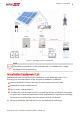
Chapter 1: Overview 7 Figure 1: StorEdge system components NOTE PV modules connected to power optimizers are not mandatory for charge/ discharge profile programming. Installation Equipment List Standard tools can be used during the installation of the SolarEdge system.
8 Installation Equipment List the mounting brackets to the mounting surface the power optimizer to the racking Wire cutters (for wires of up to 4/0 AWG) Wire strippers (for wires of up to 4/0 AWG) Voltmeter For installing the communication options, you may also need the following: For Ethernet: CAT5/6 twisted pair Ethernet cable with RJ45 connector If using a CAT5/6 cable spool: RJ45 plug and RJ45 crimper For RS485: Four- or six-wire shielded twisted pair cable Watchmaker precision screwdriver set Backup
Chapter 2: Installing and Connecting the Backup Interface Chapter 2: Installing and Connecting the Backup Interface This section explains how to install the Backup Interface and connect it to the inverter, AC loads panel and grid.
10 Installing the Conduit Holder To mount the Backup Interface: 1. Determine the Backup Interface mounting location, on a wall, stud framing or pole. It is recommended to mount the Backup Interface in a location protected from direct sunlight. 2. To allow proper heat dissipation, maintain at least a 4" clearance between the Backup Interface and other objects. 3. Position the mounting bracket against the wall/pole and mark the drilling hole locations. 4. Drill the holes and mount the bracket.
Chapter 2: Installing and Connecting the Backup Interface To install the conduit holder: 1. Insert the conduit holder in the space between the fins of the heat sink and the mounting surface. 2. Slide the conduit holder first to the left and then down to hang it on the short fin and the bolt affixed to the outer left fin. Figure 3: Installing the Backup Interface 3. Mark spots for drilling on the mounting surface. Figure 4: Marking drilling spots 4. Remove the conduit holder.
12 Installing the Conduit Holder 5. Drill two holes where marked. Figure 5: Drilling holes 6. Install the conduit holder. 7. Tighten the conduit holder to the mounting surface with two screws. Figure 6: Securing the conduit holder with screws 8. Tighten the conduit holder to the outer left fin with the supplied screw. Tighten the screw with a torque of 41 lb*in / 4.7 N*m. Backup Interface Installation Guide MAN-01-00728-1.
Chapter 2: Installing and Connecting the Backup Interface Backup Interface Interfaces The following figure shows the Backup Interface interfaces for operating and connecting to other system components. Install cable conduits, as required by local regulations. Figure 7: Backup Interface Interfaces Inverter AC inputs - AC cables from up to three inverters. Generator AC input - an AC cable from one external generator. Grid AC input - an AC cable from the grid.
14 Connecting the Backup Interface to the Grid and AC Loads Panel To connect to the Grid and Loads panels 1. Release the six Allen screws of the Backup Interface cover and remove the cover. NOTE Do not remove the internal plastic cover (dead front). 2. Install a conduit of the required diameter into the Loads conduit entry. Use the conduit holder to support the conduit. 3. Install a conduit of the required diameter into the Grid conduit entry. Use the conduit holder to support the conduit. 4.
Chapter 2: Installing and Connecting the Backup Interface 15 10. Connect the Line 1 and Line 2 wires to the grid's line terminal. Tighten the terminal screws with a torque of 200 lb*in / 22.5 N*. Figure 9: Connection to the Grid 11. Reinstall the plastic covers onto the loads terminals.
16 Connecting the Backup Interface to the Inverter d. Connect the cable wires to the 7-pin connector, as shown below, and reconnect the connector to the slot: Figure 10: Communication and 12V cables connection between Backup Interface and Inverter 3. Connect the cables to the Backup Interface: a. Pass the cables through the Com 1 conduit. b. Remove the 7-pin connector from the Backup Interface's communication slot. c. Connect the communication cable to the 7-pin connector, as shown above.
Chapter 2: Installing and Connecting the Backup Interface 17 2. Install a conduit of the required diameter into the Backup Interface's Inv1 conduit entry. 3. Pass the other end of the AC cable through the Inv1 conduit. Figure 12: AC connection between the Backup Interface and Inverter 4. Connect the L1 and L2 wires of the AC cable to the Inv1 terminal block, as shown above. Apply a torque of 22 in*lb (2 N*m). 5. Connect the Neutral wire to the Neutral bar. 6.
18 Connecting the Backup Interface to an External Rapid Shutdown Switch To connect to an External Rapid Shutdown Switch 1. Pass the cable form the switch through the Com 2 conduit. Figure 13: External rapid shutdown switch connection 2. Remove the 2-pin connector labeled EXT RSD. 3. Remove the short circuit jumper from the 2-pin connector. 4. Connect the cable to the 2-pin connector, as shown above. 5. Insert the 2-pin connector back into the EXT RSD port. 6.
Chapter 3: System Configuration 19 Chapter 3: System Configuration This chapter explains how to configure your Backup Interface using the SetApp mobile application. Before you begin, make sure the inverter firmware version is 4.8xx or higher. For information on updating your inverter firmware, refer to the Inverter Installation Guide. To set up communication with the Energy Meter 1. Make sure the StorEdge Connection Unit switch is OFF. 2. Switch the inverter ON/OFF/P switch to OFF. 3.
20 Chapter 3: System Configuration To enable Backup Configuration: Open SetApp and select Commissioning > Power Control > Energy Manager > Backup Configuration > Backup > Enable. After the Backup Configuration is enabled, the Backup Interface is automatically configured. Backup Interface Installation Guide MAN-01-00728-1.
Troubleshooting 21 Troubleshooting Error Code Error Message 26x4 Backup Interface state inconsistent 26x5 Backup Interface state inconsistent 26x6 Backup Interface state inconsistent 26x7 26xF 26x11 26x12 26x14 3xBD Backup Interface thresholds error Inverter doesn't lower AC voltage Backup Interface low temperature Backup Interface high temperature Phase imbalance too high Backup Interface comm error Troubleshooting Manually switch the Backup Interface to on-grid (see Manually Switching the Sys
22 Appendix A: Manually Switching the System to the Grid-connected Mode Appendix A: Manually Switching the System to the Grid-connected Mode In case of a Backup Interface failure or when necessary, you can reconnect the system to AC power from the grid. NOTE When the system is manually switched to the grid-connected mode, no backup of the loads is possible. To switch to the grid-connected mode: 1. Switch the ON/OFF switch of the Backup Interface to OFF. 2. Switch the inverter ON/OFF/P switch to OFF. 3.
Appendix B: Connecting External CTs Appendix B: Connecting External CTs If the Backup Interface does not disconnect all house loads in case of an outage, external Export/Import current transformers (CTs) must be connected to the Energy Meter inside the Backup Interface. Required Equipment Two split core or flexible coil CTs (available from SolarEdge). For flexible coil CTs, the power supply must be purchased separately. Extension cable - a CAT5e shielded cable To connect external CTs: 1.
24 Appendix B: Connecting External CTs 8. Disconnect the internal CT wires from the connectors. Figure 16: Disconnecting internal CTs 9. Insulate the internal CT wires. 10. Connect the external CTs twisted pairs from the extension cable to the connectors (L1 to L1; L2 to L2). 11. Reinstall the Backup Interface cover and tighten it with the screws. Apply a torque of 2.2 lb*ft /3 N*m. 12. If necessary, switch the inverter ON/OFF/P switch to ON. Backup Interface Installation Guide MAN-01-00728-1.
Appendix C: System Performance LED Indication Appendix C: System Performance LED Indication The three LEDs, visible both on the Backup Interface outer cover and inner cover, indicate the following system states: LED AC – Green Comm – Blue On Backup Interface is Communication in the backup with the inverter is mode OK Blinking - turns on and off for the same duration Backup Interface is in the gridconnected mode Off All LEDs off --- --- Fault – Red Error --- No communication No errors with the i
26 Appendix D: StorEdge Backup Interface Technical Specifications Appendix D: StorEdge Backup Interface Technical Specifications PN AC FROM GRID AC current input AC output voltage (nominal) AC output voltage range AC frequency (nominal) AC frequency range Microgrid interconnection device Grid disconnection switchover time AC TO MAIN DISTRIBUTION PANEL Maximum AC current output AC L-L output voltage (nominal) AC L-L output voltage range AC Frequency (nominal) AC Frequency range Maximal inverters AC current
Appendix D: StorEdge Backup Interface Technical Specifications GENERATOR Maximum rated AC power Maximum continuous input current Dry contact switch voltage rating Dry contact switch current rating 2-wire Start Switch ADDITIONAL FEATURES Number of communication inputs Communication Energy Meter (for Import/Export) Manual control over microgrid interconnection device STANDARD COMPLIANCE Safety Emission INSTALLATION SPECIFICATIONS Supported inverters AC from grid conduit size / AWG range AC inverter conduit s
28 Support Contact Information Support Contact Information If you have technical problems concerning SolarEdge products, please contact us: https://www.solaredge.com/service/support Before contact, make sure to have the following information at hand: Model and serial number of the product in question. The error indicated on the product SetApp mobile application or on the monitoring platform or by the LEDs, if there is such an indication.