
Installation Manual
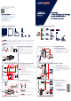
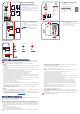
Table Of Contents

What’s in the Package
Installation and
Operation Guide
Version v. 1.5
SolarEdge
Home Battery (High Voltage)
for use with SolarEdge inverters
North America and Australia
© SolarEdge Technologies, Ltd.
All rights reserved.
Version: 1.5, March 2022
Subject to change without notice.
Sol arEdge Home
Battery
Mo unting bracket
Decorative cover
Required Personnel and Tools
WARNING!
Before installing or operating the SolarEdge Home Battery (referred to as the “Battery”), read the Safety and Handling
instructions at the back of this page.
x 2
C over
s c r ews
Dolly with lift
and ratchet straps
Drill
Mounting
s c r ews -
max M10
min 2
Mi n 2 qualified
i n s tallers
MC4
c rimper
L ev el
H andles (available
from SolarEdge)
x 4
DC cable
600V insulated
Branch connectors
( optional, available
from SolarEdge)
x 2
T orque
w r ench
Phillips
sc r ewdriver
x 2
Mounting
b r a cke t screws
MC4
connectors
Support Contact Information
In case of any technical issues with SolarEdge
products, please contact us at:
https://www.solaredge.com/service/support
Conduit
h ol der
SolarEdge
H ome Network
plug-in (available
from SolarEdge)
4
2
3
Hang battery on
mounting bracket
1. Lift the battery to the height of the mounting bracket.
2. Hang the battery on the mounting bracket, while
holding it by the handles.
3. Secure with a mounting bracket screw (supplied) on
each side. Apply a torque of 42 in-lbs/4.7N*m.
1
2
4
5
Prepare cables
1. Mount the conduit holder.
2. Pass the DC cables and grounding cable through the
conduit holder at the bottom of the battery.
3. Connect the grounding cable to the grounding terminal
with a torque of 66 in*lbs/7.5 N*m.
4. Crimp the DC cables to the MC4 connectors (supplied)
and tighten the MC4 connector glands with a torque of
30 in*lbs/3.4N*m.
3
1
Connect to inverter
1. Make sure the inverter is OFF.
2. Connect the DC cables to the DC+ and DC- inputs.
Observe correct polarity.
3. Install the SolarEdge
Home Network plug-in and antenna
in the inverter.
See the installation guide:
4. Connect cables to the inverter.
See the
Connection and Configuration
application note.
-
+
2
6
3
H ome Network
OFF
4
1
WARNING!
This symbol on the product or in the accompanying documentation denotes a hazard. It calls attention to a procedure
that, if not correctly performed or adhered to, could result in injury or loss of life. Do not proceed beyond a warning
note until the indicated conditions are fully understood and met.
Install mounting bracket
1. Level the bracket.
2. Mark two drilling spots.
Use either the inner or outer pair of holes.
If necessary, you can use the additional holes to secure
the bracket.
3. Drill holes in the installation surface.
4. Install the mounting bracket and secure with screws.
When selecting the installation location:
• Maintain a clearance of min 8 in/20 cm from other objects.
• Make sure the max distance from the inverter is max
164 ft/50 m.
Make sure the installation surface sustains the weight of the
battery (267lbs/121kg).
16” / 40.5 cm
24” / 61 cm
2
3
4
2
1
min 8 in/20 cm
m a x 164 ft/5 0 m
For the SolarEdge Home Battery – Emergency
Response guide, including emergency phone
numbers, scan the QR code:
Fire
extinguisher
Transport battery
1. Screw in all FOUR handles to the battery frame.
2. Place the battery upright on a dolly and secure it with
straps.
Caution!
Stand the battery on the rubber protector only!
3. Transport the battery to the installation location.
;
1
2
3
3
CAUTION!
Make sure to screw in the handles all the way.
Do not use a bent, cracked, or otherwise damaged handle.
Install fire extinguisher
Long-nose
pliers
1
1
2
3
3
1 4
1. Use long-nose pliers to straighten and remove the
safety pin.
2. Remove the sticker that covers the fire extinguisher’s
service hole.
3. Carefully insert the fire extinguisher into the service
hole.
4. Secure the fire extinguisher with seven Allen screws
(supplied). Apply a torque of 40 in-lbs/4.5N*m.