
Installation Guide Manual
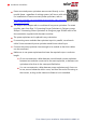
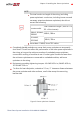
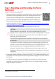
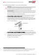
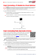
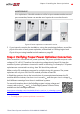
Table Of Contents
- Disclaimers
- Support and Contact Information
- Revision History
- Contents
- HANDLING AND SAFETY INSTRUCTIONS
- IMPORTANT SAFETY INSTRUCTIONS
- Chapter 1: Introducing the SolarEdge Power Harvesting System
- Chapter 2: Installing the Power Optimizers
- Chapter 3: Installing the Inverter
- Chapter 4: Connecting the AC and the Strings to the Safety Switch
- Chapter 5: Commissioning the Installation
- Chapter 6: User Interface
- Chapter 7: Setting Up Communication
- Appendix A: Errors and Troubleshooting
- Appendix B: Mechanical Specifications
- Appendix C: External Fan Maintenance and Replacement
- Appendix D: Replacing and Adding System Components
- Appendix E: Determining the Circuit Breaker Size
- Technical Specifications - Single Phase Inverters (North America)
- Technical Specifications - Three Phase Inverters (North America)

NOTE
The total conductor length of the string (excluding
power optimizers’ conductors; including home runs and
necessary extensions between optimizers) should not
exceed the following:
Inverter model
Total conductor length ( from DC+ to
DC- of the inverter)
SE9KUS, SE10KUS,
SE20KUS
1000 ft. /300 m
SE14.4KUS,
SE33.3KUS
2300 ft./ 700 m
Use at least 11 AWG/ 4 mm² DC cables.
Completely shaded modules may cause their power optimizers to temporarily
shut down. This will not affect the performance of the other power optimizers in
the string, as long as the minimum number of unshaded power optimizers
connected in a string of modules is met. If under typical conditions fewer than
the minimum optimizers are connected to unshaded modules, add more
optimizers to the string.
Equipment grounding tightening torques: 4-6 AWG: 45 lb-in, 8 AWG: 40 lb-in,
10-14 AWG: 35 lb-in.
To allow for heat dissipation, maintain a 2.5 cm / 1" clearance distance between
the power optimizer and other surfaces, on all sides except the mounting
bracket side.
Figure 3: Power optimizer clearance
Chapter 2: Installing the Power Optimizers 23
Three Phase System Installation Guide MAN-01-00002-4.3