
Installation Guide Manual
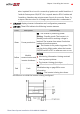
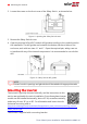
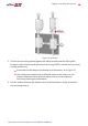
Table Of Contents
- Disclaimers
- Support and Contact Information
- Revision History
- Contents
- HANDLING AND SAFETY INSTRUCTIONS
- IMPORTANT SAFETY INSTRUCTIONS
- Chapter 1: Introducing the SolarEdge Power Harvesting System
- Chapter 2: Installing the Power Optimizers
- Chapter 3: Installing the Inverter
- Chapter 4: Connecting the AC and the Strings to the Safety Switch
- Chapter 5: Commissioning the Installation
- Chapter 6: User Interface
- Chapter 7: Setting Up Communication
- Appendix A: Errors and Troubleshooting
- Appendix B: Mechanical Specifications
- Appendix C: External Fan Maintenance and Replacement
- Appendix D: Replacing and Adding System Components
- Appendix E: Determining the Circuit Breaker Size
- Technical Specifications - Single Phase Inverters (North America)
- Technical Specifications - Three Phase Inverters (North America)

Figure 9: Inverter Interfaces
AC and DC conduit entries: Connection points of the Safety Switch.
Two communication glands, for connection of inverter communication
options. Each gland has three openings. Refer to
Setting Up Communication
on
page 83 for more information.
LCD light button: Pressing this button lights up the LCD for 30 seconds. In
addition, you can press this button to view inverter status screens and access
configuration menu options, as described
Configuring the Inverter Using the
LCD Light Button
on page 64.
ON/OFF switch: Turning this switch ON (after the power optimizers are paired
with the inverter) starts the operation of the power optimizers, enables power
production and allows the inverter to begin exporting power to the utility grid.
Turning it OFF reduces the power optimizer voltage to a low safety voltage and
inhibits exportation of power. When this switch is OFF, the inverter control
circuitry remains powered up.
WARNING!
For inverters with manual Rapid Shutdown (PVRSS) functionality - Upon
PVRSS, the internal circuitry remains up, therefore the inverter cover
must be opened only after shutting off the inverter ON/OFF switch. This
disables the DC voltage inside the inverter. Wait five minutes before
opening the cover. Otherwise, there is a risk of electric shock from
energy stored in the capacitors.
AVERTISSEMENT!
A la Coupure Rapide (PVRSS) les circuits internes restent actifs, il est
-Three Phase System Installation Guide MAN-01-00002-4.3
32 Inverter Interfaces