
Installation Guide Manual
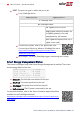
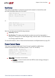
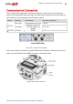
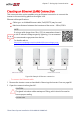
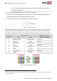
Table Of Contents
- Disclaimers
- Support and Contact Information
- Revision History
- Contents
- HANDLING AND SAFETY INSTRUCTIONS
- IMPORTANT SAFETY INSTRUCTIONS
- Chapter 1: Introducing the SolarEdge Power Harvesting System
- Chapter 2: Installing the Power Optimizers
- Chapter 3: Installing the Inverter
- Chapter 4: Connecting the AC and the Strings to the Safety Switch
- Chapter 5: Commissioning the Installation
- Chapter 6: User Interface
- Chapter 7: Setting Up Communication
- Appendix A: Errors and Troubleshooting
- Appendix B: Mechanical Specifications
- Appendix C: External Fan Maintenance and Replacement
- Appendix D: Replacing and Adding System Components
- Appendix E: Determining the Circuit Breaker Size
- Technical Specifications - Single Phase Inverters (North America)
- Technical Specifications - Three Phase Inverters (North America)

Le cote interne du gland contient une rondelle qui doit être utilisée pour
une bonne étancheïté.
3. Remove the plastic seal from one of the large opening .
4. Remove the rubber fitting from the gland and insert the CAT5/6 cable through the
gland and through the gland opening in the inverter .
5.
Push the cable into the cut opening of the rubber fitting.
Figure 31: Rubber fitting
CAT5/6 standard cables have eight wires (four twisted pairs), as shown in the diagram
below. Wire colors may differ from one cable to another. You can use either wiring
standard, as long as both sides of the cable have the same pin-out and color-coding.
RJ45 Pin #
Wire Color
(1)
10Base-T Signal
100Base-TX Signal
T568B T568A
1 White/Orange White/Green Transmit+
2 Orange Green Transmit-
3 White/Green White/Orange Receive+
4 Blue Blue Reserved
5 White/Blue White/Blue Reserved
6 Green Orange Received-
7 White/Brown White/Brown Reserved
8 Brown Brown Reserved
Figure 32: Standard cable wiring
(1)
The inverter connection does not support RX/TX polarity change. Supporting crossover Ethernet cables depends on
the switch capabilities.
-Three Phase System Installation Guide MAN-01-00002-4.3
88 Creating an Ethernet (LAN) Connection