
Installation Guide Manual
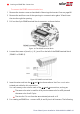
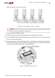
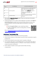
Table Of Contents
- Disclaimers
- Support and Contact Information
- Revision History
- Contents
- HANDLING AND SAFETY INSTRUCTIONS
- IMPORTANT SAFETY INSTRUCTIONS
- Chapter 1: Introducing the SolarEdge Power Harvesting System
- Chapter 2: Installing the Power Optimizers
- Chapter 3: Installing the Inverter
- Chapter 4: Connecting the AC and the Strings to the Safety Switch
- Chapter 5: Commissioning the Installation
- Chapter 6: User Interface
- Chapter 7: Setting Up Communication
- Appendix A: Errors and Troubleshooting
- Appendix B: Mechanical Specifications
- Appendix C: External Fan Maintenance and Replacement
- Appendix D: Replacing and Adding System Components
- Appendix E: Determining the Circuit Breaker Size
- Technical Specifications - Single Phase Inverters (North America)
- Technical Specifications - Three Phase Inverters (North America)

Creating an RS485 Bus Connection
The RS485 option enables creating a bus of connected inverters, consisting of up to 31
slave inverters and 1 master inverter. Using this option, inverters are connected to each
other in a bus (chain), via their RS485 connectors. The first and last inverters in the
chain must be terminated as described on page 93.
RS485 wiring specifications:
Cable type: Min. 3-wire shielded twisted pair (a shielded Ethernet cable (Cat5/5E
STP) may be used)
Wire cross-section area: 0.2- 1 mm²/ 24-18 AWG (a CAT5 cable may be used)
Maximum nodes: 32
Maximum distance between first and last devices: 1 km /3300 ft.
NOTE
If using a cable longer than 10 m/33 ft in areas where there is a
risk of induced voltage surges by lightning, it is recommend to
use external surge protection devices. For details refer to:
https://www.solaredge.com/sites/default/files/overvoltage_surge_
protection_na.pdf.
If grounded metal conduit are used for routing the communication wires, a
lightning protection device is not required.
If not using surge protection, connect the grounding wire to the first inverter
in the RS485 chain; ensure it is not in contact with other wires. Connect the
grounding wire to the grounding bus-bar in the Safety Switch.
NOTE
An additional RS485 port (RS485-Plug-in) is available from
SolarEdge, allowing the creation of RS485 Bus Connection; Refer
to
The following sections describe how to physically connect the RS485 bus and how to
configure the bus.
Chapter 7: Setting Up Communication 91
Three Phase System Installation Guide MAN-01-00002-4.3