
Installation Guide Manual
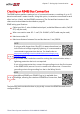
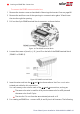
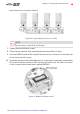
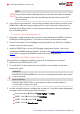
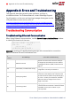
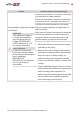
Table Of Contents
- Disclaimers
- Support and Contact Information
- Revision History
- Contents
- HANDLING AND SAFETY INSTRUCTIONS
- IMPORTANT SAFETY INSTRUCTIONS
- Chapter 1: Introducing the SolarEdge Power Harvesting System
- Chapter 2: Installing the Power Optimizers
- Chapter 3: Installing the Inverter
- Chapter 4: Connecting the AC and the Strings to the Safety Switch
- Chapter 5: Commissioning the Installation
- Chapter 6: User Interface
- Chapter 7: Setting Up Communication
- Appendix A: Errors and Troubleshooting
- Appendix B: Mechanical Specifications
- Appendix C: External Fan Maintenance and Replacement
- Appendix D: Replacing and Adding System Components
- Appendix E: Determining the Circuit Breaker Size
- Technical Specifications - Single Phase Inverters (North America)
- Technical Specifications - Three Phase Inverters (North America)

To connect the RS485 communication bus:
1. Remove the inverter cover as described in
Removing the Inverter Cover
on page 86.
2. Remove the seal from one of the openings in communication gland #2 and insert
the wire through the opening.
3.
Pull out the 6-pin RS485 terminal block connector, as shown below:
Figure 34: The RS485 terminal block
4.
Loosen the screws of pins A(+), B(-), and G on the left of the RS485 terminal block
(RS485-1 or RS485-2).
Figure 35: RS485 terminal block
5.
Insert the wire ends into the G, A and B pins shown above. Use Four- or six-wire
twisted pair cable for this connection.
You can use any color wire for each of the A, B and G connections, as long as:
The same color wire is used for all A pins the same color for all B pins and
the same color for all G pins
The wire for G is not from the same twisted pair as A or B.
6.
For creating an RS485 bus - connect all B, A and G pins in all inverters. The following
-Three Phase System Installation Guide MAN-01-00002-4.3
92 Creating an RS485 Bus Connection