
User Guide


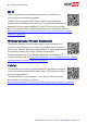

Table Of Contents

Creating an Ethernet (LAN) Connection
This communication option enables using an Ethernet connection to connect the
inverter to the monitoring platform through a LAN.
Figure 1: Example of Ethernet connection
Ethernet cable specifications:
Cable type – a shielded CAT6 Ethernet cable
Maximum distance between the inverter and the router – 100 m/ 330 ft.
NOTE
If using a cable longer than 10 m / 33 ft in areas where there is
a risk of induced voltage surges by lightning, it is recommend
to use external surge protection devices.
For details refer to:
http://www.solaredge.com/files/pdfs/lightning_surge_
protection.pdf.
To connect the Ethernet cable:
1. Remove the invertercover as described above.
2. Open Communication Gland 1.
CAUTION!
The gland includes a rubber waterproof fitting, which should be used to
ensure proper sealing.
3. Remove the plastic seal from one of the large openings.
4. Remove the rubber fitting from the gland and insert the CAT6 cable through the
gland and through the gland opening in the inverter.
5.
Push the cable into the cut opening of the rubber fitting.
Chapter 2: Setting Up Communication with the Monitoring Platform 8
Communication Board for Inverters with SetApp Configuration