SolarEdge SolarEdge Electricity Meter Installation Guide For North America Version 1.
Disclaimers Disclaimers Important Notice Copyright © SolarEdge Inc. All rights reserved. No part of this document may be reproduced, stored in a retrieval system or transmitted, in any form or by any means, electronic, mechanical, photographic, magnetic or otherwise, without the prior written permission of SolarEdge Inc. The material furnished in this document is believed to be accurate and reliable. However, SolarEdge assumes no responsibility for the use of this material.
Contents Contents Disclaimers Important Notice FCC Compliance Contents HANDLING AND SAFETY INSTRUCTIONS Safety Information Chapter 1: Introduction Terminology The SolarEdge Electricity Meter Meter Connection Options Chapter 2: Meter Installation Installation Guidelines Installing and Connecting the Meter Chapter 3: SolarEdge Device Configuration Appendix A: Troubleshooting Meter Connection Communication Status Screen Troubleshooting Device Type or Protocol are configured incorrectly Number of devices is no
HANDLING AND SAFETY INSTRUCTIONS HANDLING AND SAFETY INSTRUCTIONS During installation, testing and inspection, adherence to all the handling and safety instructions is mandatory. Failure to do so may result in injury or loss of life and damage to the equipment. Safety Information The following safety symbols are used in this document. Familiarize yourself with the symbols and their meaning before installing or operating the system. WARNING! Denotes a hazard.
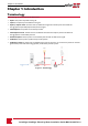
Chapter 1: Introduction Chapter 1: Introduction Terminology The following terms are used in this document: l Export: The power injected to the grid. l Import: The power purchased from the grid. l Export/ Import meter: A meter that is installed at the grid connection point and reads the energy/power exported/imported to/from the grid. l Consumption: The power consumed by the site. l Consumption meter: A meter that is installed at the load consumption point and reads the energy/power consumed by the site.
Chapter 1: Introduction The SolarEdge Electricity Meter The SolarEdge meter enables measuring the power and energy of the photovoltaic (PV) system. The meter is used by the inverter for the following applications: l Consumption monitoring l Export limitation l StorEdge Smart Energy Management on-grid applications The meter is built into an enclosure and requires two Current Transformers (CTs; available from SolarEdge).
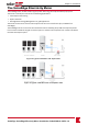
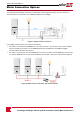
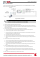
Meter Connection Options Meter Connection Options In a single inverter system, the meter is connected directly to the inverter. If your inverter has a built-in revenue grade meter (RGM; the inverter is referred to a revenue grade inverter), you can connect an external meter on the same bus as the RGM (available form SolarEdge). Figure 4: Single-inverter connection In a multiple inverter system, two options are available: l The meter is connected to the RS485 port of one of the inverters.
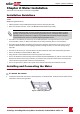
Chapter 2: Meter Installation Chapter 2: Meter Installation The meter is connected to the inverter using RS485. Installation Guidelines AC wire specifications: 1.3 to 2.0 mm diameter / 16-12 AWG stranded wire, 600 V, type THHN, MTW, or THWN. RS485 wiring specifications: l Cable type: Min. 3-wire shielded twisted pair (a 4-wire cable may be used) l Wire cross-section area: 0.
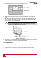
Installing and Connecting the Meter 2. Loosen the 4 Allen screws of the meter enclosure and remove the cover. Figure 7: Meter front view without cover 3. Carefully move the terminal block end-stops to the sides of the meter and remove the terminal blocks. 4. Open one or more conduit knockouts according to the conduits used in the installation: Open the required knockout(s), each with two sizes: ¾'' and 1'', taking care not to interfere with any of the internal components. A Unibit drill may be used.
Chapter 2: Meter Installation To wire the meter: If you are connecting the meter to a revenue grade inverter, refer to Installing Two Meters on page 19. Refer to the connection diagram below: Figure 9: Meter connections NOTE l Clamp the CT connected to L1 CT around the wire connected to ØL1. l Clamp the CT connected to L2 CT around the wire connected to ØL2. 1. Verify that power is OFF before making connections. 2.
Installing and Connecting the Meter To connect the meter to the inverter or CCG: 1. If connecting to an inverter, remove the seal from one of the openings in communication gland #2 at the bottom of the inverter and insert the RS485 wires from the meter through the opening. Figure 10: Communication glands 2. Prepare to connect to one of the available RS485 ports of the device, as shown below: l Inverter RS485-1 - pull out the 9-pin RS485 connector located on the communication board.
Chapter 2: Meter Installation 3. Connect the wires as shown below: Figure 14: Meter RS485 connections 4. If the SolarEdge device is at the end of the RS485 bus, terminate as follows: l l Inverter - Terminate by switching a termination DIP-switch inside the inverter to ON (top position). The switch is located on the communication board and is marked SW7. CCG - Terminate by switching the SW2 termination DIP-switch to ON.
Chapter 3: SolarEdge Device Configuration Chapter 3: SolarEdge Device Configuration This section describes basic configuration of SolarEdge devices (inverter/CCG) for using a meter. In addition, configuration specific to the application being used is required in some cases. Refer to the following documents: l Export Limitation - http://www.solaredge.us/files/pdfs/products/export_limitation_application_ note_NA.pdf l Consumption and Production Monitoring http://www.solaredge.
Chapter 3: SolarEdge Device Configuration 6. Select Device Type. the following screen is displayed: SolarEdge Non-SE Logger Meter Multi-devices Revenue None 7. Select Revenue Meter, the following screen is displayed: Device Type Protocol Device CT ID <1> Rating <0> Meter Func. 8. Configure the meter parameters as follows: l Select Protocol è WattNode. l Select Device ID: 2 l Set the CT rating to the value that appears on the CT: CT Rating è .
Chapter 3: SolarEdge Device Configuration To verify meter connection: 1. Press the Enter button or the LCD external button until the Communication status screen is displayed as shown below. This screen shows the number of external devices that communicate on each port, the device type, and the protocol to which each port was configured. 2. Verify that the setting of the relevant RS485 port is correct and that the port is communicating with the meter.
Appendix A: Troubleshooting Meter Connection Appendix A: Troubleshooting Meter Connection SolarEdge revenue grade inverters have a built in Revenue Grade Meter (RGM). For troubleshooting RGMs, refer to http://www.solaredge.com/files/pdfs/built-in_rgm_troubleshooting.pdf. This section describes how to troubleshoot meter-related installation and performance errors.
is not displayed is not displayed If is not displayed in the Status line of the status screen shown above, the meter is not communicating with the inverter. Check the following: l There are no loose connections at the inverter communication board and at the meter. l The wiring between the black 4-pin terminal block on the meter and the RS485 terminal block on the communication board is correct.
Appendix A: Troubleshooting Meter Connection Meter Status LEDs Power Status LEDs The three status LEDs on the front of the meter can help indicate correct measurements and operation. l Normal operation indications: At normal startup - when power is first applied, all the LEDs light up sequentially for 1 sec.
Modbus Communication LEDs Modbus Communication LEDs The communication LED is located at the upper left corner. The following are indications of the LED light: LED color Function Indication Troubleshooting Flashing An invalid packet: bad baud rate, bad CRC, noise, bad parity, etc. Check that the communication wires are connected correctly. ON The address is set to zero: an invalid choice Check that the Device ID is set to 2 in the RS485 Conf screen.
Appendix B: Installing Two Meters Appendix B: Installing Two Meters This section describes connecting an external meter to an inverter equipped with a built-in Revenue Grade Meter (RGM), which is located in the Safety Switch. RS485 wiring is daisy-chained between the two meters and the inverter. Connecting Two Meters 1. Connect the external meter to the RGM as shown in Figure 17: a. Route the external meter wires through one of the Safety Switch conduits (it is recommended to use the DC side conduits). b.
Verifying Meter Connection 2. Select Device Type. the following screen is displayed: SolarEdge Non-SE Logger Meter Multi-devices Revenue None 3. Select Multi Devices. The following screen is displayed: Device Type Meter 1 Meter 2 <-- -> Meter 3 <-- -> 4. Select Meter 1. The following is displayed for the RGM: Device Type Protocol Device CT ID Rating Meter <1> <5A> Func. 5.
Appendix B: Installing Two Meters ## : The number of communicating meters. For dual meters it should display 2. If not, refer to Troubleshooting below. 2. Press the Enter button or the LCD external button until reaching the Meter status screen showing the total energy [Wh]. There is a status screen for each meter function. For example, for an export+import meter and a production meter, there will be three status screens: for export, import and production.
Appendix C: Meter Information Displayed in the Monitoring Portal Appendix C: Meter Information Displayed in the Monitoring Portal If your device is connected to the SolarEdge server, you can view the meter’s readings in the monitoring portal.
Appendix D: Meter Technical Specifications Appendix D: Meter Technical Specifications SE-MTR240-2-200-S1 SE-MTR240-2-400-S1 UNITS ELECTRICAL SERVICE Operating Voltage Range - Line to Line AC Frequency Grids Supported 211 - 264 Vac 60 Hz L1 / L2 / N / PE Power Consumption (typ.) 1.2 W COMMUNICATION Supported Communication Interfaces RS485 Response time ≤1 Device ID (Modbus) sec 2 ACCURACY (@ 77°F / 25°C, PF:0.
Appendix E: External Lightning Protection Connection Appendix E: External Lightning Protection Connection Protection devices are most often installed from each data line to the local earth ground, and should be selected to begin conducting current at a voltage as close to the system's normal communication level as possible, but never lower. For RS485 communication lines, the selected voltage rating is typically 6-8 V.