Installation Guide Energy Meter with Modbus Connection For North America Version 1.
Disclaimers 1 Disclaimers Important Notice Copyright © SolarEdge Inc. All rights reserved. No part of this document may be reproduced, stored in a retrieval system or transmitted, in any form or by any means, electronic, mechanical, photographic, magnetic or otherwise, without the prior written permission of SolarEdge Inc. The material furnished in this document is believed to be accurate and reliable. However, SolarEdge assumes no responsibility for the use of this material.
2 FCC Compliance Connect the equipment into an outlet on a circuit different from that to which the receiver is connected. Consult the dealer or an experienced radio/TV technician for help. Changes or modifications not expressly approved by the party responsible for compliance may void the user’s authority to operate the equipment. Energy Meter with Modbus Connection MAN-01-00270-1.
Version History Version History Version 1.3 (August 2019) Added notation of default DIP switch settings Added label to meter showing CT connections Corrected description of LED indicators Version 1.2 (February 2019) Meter uses Wye topology configuration. Version 1.1 (January 2019) Updated for new meter hardware Addition of configuration via SetApp Version 1.0 (April 2017) - Initial release Energy Meter with Modbus Connection MAN-01-00270-1.
4 Contents Contents Disclaimers Important Notice FCC Compliance 1 1 1 Version History 3 Contents 4 HANDLING AND SAFETY INSTRUCTIONS Safety Symbols Information 5 5 Chapter 1: Introduction Terminology The SolarEdge Energy Meter with Modbus Connection Meter Interfaces Meter Connection Meter Connection Options 6 6 6 7 9 10 Chapter 2: Meter Installation Transport and Storage Package Contents Installation Equipment Installation Guidelines Installing and Connecting the Meter 12 12 12 12 12 13 Chapter
HANDLING AND SAFETY INSTRUCTIONS 5 HANDLING AND SAFETY INSTRUCTIONS During installation, testing and inspection, adherence to all the handling and safety instructions is mandatory. Failure to do so may result in injury or loss of life and damage to the equipment. Safety Symbols Information The following safety symbols are used in this document. Familiarize yourself with the symbols and their meaning before installing or operating the system. WARNING! Denotes a hazard.
6 Chapter 1: Introduction Chapter 1: Introduction Terminology The following terms are used in this document: Export: The power injected to the grid. Import: The power purchased from the grid. Export/Import meter: A meter that is installed at the grid connection point and measures the energy/power exported/imported to/from the grid. Consumption: The power consumed by the site. Consumption meter: A meter that is installed at the load consumption point and measures the energy/power consumed by the site.
Chapter 1: Introduction The meter is used by the inverter for the following applications: Production metering Consumption monitoring Export limitation Smart Energy on-grid applications The meter is built into an enclosure and requires two Current Transformers (CTs). The CTs are available from SolarEdge. Meter Interfaces This section describes the meter's external and internal interfaces.
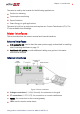
8 Meter Interfaces ID DIP switches (ID 1, 2, 3): used to set the Modbus address. Termination DIP switches (TERM 1, 2): used to set RS485 termination. LEDs The meter utilizes the LEDs at the top of the unit in order to indicate current status.
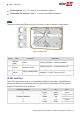
Chapter 1: Introduction Modbus Address 5 6 7 ID 1 Up Down Up ID 2 Down Up Up 9 ID 3 Up Up Up Termination DIP switches The Termination DIP switches are used to configure RS485 wiring termination. The termination options are listed in the table below. See the figureID and Termination DIP Switches on page 9 for switch direction guidelines.
10 Meter Connection Options Figure 5: Typical installation with production meter Figure 6: Typical installation with export/import meter Figure 7: Typical installation with consumption meter Meter Connection Options In a single inverter system, the meter is connected directly to the inverter. If your inverter has a built-in revenue grade meter (RGM; the inverter is referred to as a revenue grade inverter), you can connect an external meter on the same bus as the RGM (available from SolarEdge).
Chapter 1: Introduction Figure 8: Single-inverter connection In a multiple inverter system, the meter is connected to the RS485 port of one of the inverters. If the inverter has only one RS485 bus, use an RS485 Plug-in (available from SolarEdge) or wireless communications between the inverters. Energy Meter with Modbus Connection MAN-01-00270-1.
12 Chapter 2: Meter Installation Chapter 2: Meter Installation Transport and Storage Transport the Energy Meter with Modbus Connection in its original packaging, without exposing it to unnecessary shocks. If the original package is no longer available, use a similar box that can be closed fully. Store the meter in a dry place where ambient temperatures are -40°C / -40°F to +60°C / 140°F.
Chapter 2: Meter Installation 13 The meter is considered “permanently connected equipment” and requires a disconnect means (circuit breaker, switch, or disconnect) and overcurrent protection (fuse or circuit breaker). The meter draws up to 100 mA, therefore the rating of any switches, disconnects, fuses, and/ or circuit breakers is determined by the wire gauge, the mains voltage, and the current interrupting rating required.
14 Installing and Connecting the Meter be used. The rest of the drill guides (located at the bottom, back and sides of the enclosure, each with two sizes: ¾'' and 1'') should remain sealed. Figure 10: AC wiring drill guide 3. Install the bracket on a wall or pole, with the semi-circles facing downward, as shown below. Verify that the bracket is firmly attached to the mounting surface. Figure 11: Mounting bracket 4.
Chapter 2: Meter Installation 15 Figure 13: Meter - rear view 6. Mount the meter: Attach the meter enclosure's back brackets to the mounted bracket using the four supplied screws. Tighten the screws with a torque of 9 N*m / 6.6 lb*ft. To install the current transformers (CTs): CAUTION! NOTE CTs are not supplied with the meter and must be purchased separately. Rogowski coils are not suitable for use with the meter. 1. Turn off AC power before clamping on current transformers. 2.
16 Installing and Connecting the Meter To wire the meter: Wire the meter in accordance with one of the connection diagrams below: Split phase grid, see the figure Split Phase Grid on page 16 No-neutral grid, see the figure No-Neutral Grid on page 17 If you are connecting the meter to a revenue grade inverter (inverter with built-in meter), refer to Installing Two Meters on page 35. Figure 14: Split Phase Grid NOTE Clamp the CT connected to L1 CT around the wire connected to ØL1.
Chapter 2: Meter Installation 17 Figure 15: No-Neutral Grid NOTE Clamp the CT connected to L1 CT around the wire connected to ØL1. When clamping the CT around the conductor to be measured, make sure the arrow is pointing towards the grid. 1. Verify that the meter is powered OFF before making connections. 2. Insert the grounding/neutral cable, AC-side wires, CT wires, and RS485 cabling through the drill guide(s) that were opened and connect them to the meter as specified in the above diagrams. 3.
18 Installing and Connecting the Meter 2. Prepare to connect the RS485 wiring to one of the available RS485 ports of the device. Note that some inverters have one RS485 port, some have two RS485 ports. 3. Pull out the RS485 connector located on the communication board, as shown in the figure below. Figure 16: Inverter RS485 connection 4. Loosen the screws of RS485 terminal block pins B, A and G of the port you wish to connect. Figure 17: RS485 terminal block 5.
Chapter 2: Meter Installation DIP-switch inside the inverter to ON (top position). The switch is located on the communication board and is marked SW7. Figure 18: RS485 termination switch To connect the RS485 wiring to the Commercial Gateway: 1. Connect to one of one of the 3-pin connectors supplied with the Commercial Gateway to the RS485-2 connection on the Commercial Gateway. Figure 19: Commercial Gateway RS485 connector 2.
20 Installing and Connecting the Meter Figure 20: RS485 termination switch Energy Meter with Modbus Connection MAN-01-00270-1.
Chapter 3: Configuration 21 Chapter 3: Configuration Device Configuration This section describes basic configuration of SolarEdge devices (inverter/Commercial Gateway) for use of a meter. In addition, a configuration that is specific to the application being used is required in some cases. Refer to the following documents: Export Limitation - https://www.solaredge.com/sites/default/files/export_ limitation_application_note_NA.pdf StorEdge Smart Energy Management off-grid applications https://www.
22 Device Configuration Site Production: The meter is installed at the inverter output and reads the energy produced by inverters at the site. Ext. Production: The meter is used for export limitation with 3rd party generators and for AC coupling with non-SolarEdge inverters. 6. Select Meter Protocol, and select SolarEdge. 7. Select Device ID and enter the Modbus address corresponding to the ID DIP switch settings on the meter. 8. Select CT Rating and enter the current transformer's rating in amperes. 9.
Chapter 3: Configuration 23 OK/Enter (3): Selects a menu option and accepts a value change with a long press (until Applied is displayed). Use the three rightmost buttons Up, Down and OK sequentially for entering the Setup mode. Inverter Configuration – Setup Mode After inverter installation, an installer may perform basic system configuration. Configuration is done when the inverter is in Setup mode. To enter Setup mode: 1. Turn the inverter ON/OFF switch to OFF (AC remains ON).
24 Device Configuration To configure the SolarEdge meter using the device display: 1. Scroll to the Communication menu and select RS485-X Conf (X represents the actual RS485 port to which the electricity meter is connected: 1 or E for the inverter; 1 or 2 or E for the Commercial Gateway). The following screen is displayed: Device Type Protocol Device ID <1> Slave Detect <#> Long SLV Detect <#> Slave List <#> Multi-Inv. Set 2. Select Device Type è Multi Devices.
Chapter 3: Configuration 25 Select Meter Func. and select one of the functionality options, according to the installed meter specifications and location. E E C P E I N x x o r x m o p p n o t p n o o s d . o e r r u u t t m c P rt +Import ption tion roduction Export+Import: The meter is installed at the grid connection point and reads pulses from both directions - export and import energy. Export: The meter is installed at the grid connection point and reads the export energy.
26 Device Configuration Verifying the Meter Connection Verifying the Meter Connection using SetApp To verify the meter connection using SetApp: 1. From the SetApp main menu, select Status. 2. On the Status page, scroll down to the Communication status section. Check that one or more meters is connected to the RS485-1 or RS485-2 bus. Communication LAN Connected RS485-1 RS485-2 Modbus SE Slave 2 of 2 None Cellular ZigBee N/A NC 3. Continue scrolling to the Meters section.
Chapter 3: Configuration information is displayed: Meters Production Meter SN: XXXXXXXX RS485-2 Status Modbus ID #1 OK Power Energy 7.60 kW 13.68MWh Export Meter SN: XXXXXXXX GPIO S0 meter 1000 pulses per kWh Power Energy 7.60 kW 13.68MWh 4. From the SetApp main menu, select Status. Verifying the Meter Connection using the Device Display To verify the meter connection in devices with a display: 1.
28 Device Configuration D RS485-1<-><- o N - t ## >< 1> ><--> ><--> Dev: the type of device connected to this port. MTR indicates a meter. Prot: the communication protocol ## = 1: Indicates that the connection to the meter is successful. 4. Continue pressing the Enter button or the LIGHT button using short presses until reaching the meter status screen showing the Energy [Wh] total. If there is more than one meter/ function, there is a status screen for each one.
Appendix A: Troubleshooting the Meter 29 Appendix A: Troubleshooting the Meter This appendix describes how to troubleshoot meter-related installation and performance issues. To troubleshoot the meter using SetApp, refer to Troubleshooting the Meter using SetApp on page 29. To troubleshoot the meter using the device display, refer to Troubleshooting the Meter using the Device Display on page 32.
30 Troubleshooting the Meter using SetApp If the status in the Meters section of the Status page is "Comm. Error" Meters Export Meter RS485-1 Status Modbus ID #2 Comm. Error Power Energy 7.60 kW 8.42 MWh Check the following: The meter's RS485 address DIP switch settings. Refer to "ID DIP switches" on page 8. The meter's Termination DIP switch settings. Refer to "Termination DIP switches" on page 9.
Appendix A: Troubleshooting the Meter 31 The Energy Value is not Advancing Check the Energy value in the Meters section of the Status page, as shown in the figure below: Meters Export Meter RS485-1 Status Modbus ID #2 Comm. Error Power Energy 7.60 kW 8.
32 Troubleshooting the Meter using the Device Display Troubleshooting the Meter using the Device Display The communication status screen should display the following: D RS485-1<-><- o E - t ## >< 1> ><--> ><--> Device Type or Protocol are configured incorrectly If MTR (meter) is not displayed as the device type (DEV), or SE (SolarEdge) is not displayed as the Prot (protocol), configure the meter as follows.: 1.
Appendix A: Troubleshooting the Meter 33 Use a Voltmeter to measure the voltage on the meter's AC wiring. The line to line voltage should be according to the meter's specifications. is not displayed P S P E r t o n o a w e d t e r u u r g c s [ y tion Me : .x xx.x If is not displayed in the Status line of the status screen shown above, the meter is not communicating with the inverter.
34 Troubleshooting the Meter using the Device Display Check for water damage or sealing problems: Inspect the entire conduit run for possible points of water penetration, and fix leaks. Ensure that proper outdoor rated components are used. Energy Meter with Modbus Connection MAN-01-00270-1.
Appendix B: Installing Two Meters 35 Appendix B: Installing Two Meters This section describes connecting an external meter to an inverter equipped with a built-in Revenue Grade Meter (RGM), which is located in the inverter's Safety Switch. Figure 21: Connecting an external meter to an inverter with a built-in RGM Connecting Two Meters 1. Connect the external meter to the inverter as described in the section "wire the meter:" on page 16. 2. Set the external meter's ID DIP switch settings.
36 Configuring the Dual-Meter Connection Meter Function è Inverter Production Protocol èSolarEdge Device ID è 1 CT Rating è 5A 3. Select Meter 2 to configure the external meter in the following steps: 4. Select Meter Function, and choose one of the following options: Export+Import: The meter is installed at the grid connection point and reads pulses from both directions - export and import energy. Consumption: The meter is installed at the load consumption point and reads the energy consumed by the site.
Appendix B: Installing Two Meters D P D C M e r e T e vice Typ otocol < vice ID Rating ter Func 37 e WN> <1> <5A> . 4. Verify: Device Type è MTR Protocol è SE Device ID è 1 CT Rating è 5A Meter Func.è Prod (production) 5. Select Meter 2 and configure the external meter settings: Select Device Type è Revenue Meter Select Protocol èSE Set Device ID: 2 Set the CT rating to the value that appears on the CT: CT Rating è . The default is 5 Amperes.
38 Verifying the Meter Connection Verifying Meter Connection using SetApp 1. From the SetApp main menu, select Status. 2. In the Communications section of the Status page, check the value of the RS485-x field, which lists: The connection protocol (for example, Modbus, SE Master, SE Slave) "x of y", where x is the number of meters configured, and y is the number of meters connected. Verifying Meter Connection Using the Device Display 1.
Appendix B: Installing Two Meters 39 If the SolarEdge device is connected to the SolarEdge server this value will also be displayed in the monitoring platform. Troubleshooting the Dual-Meter Connection To troubleshoot the Dual-Meter connection using SetApp, Troubleshooting Dual-Meter Connection Using SetApp on page 39. To troubleshoot the Dual-Meter connection using the device display, Troubleshooting Dual-meter Connection using the Device Display on page 40.
40 Troubleshooting the Dual-Meter Connection The Energy value is not advancing Check the Energy value in the Meters section of the Status page, as shown in the figure below: Meters Export Meter RS485-1 Status Modbus ID #2 Comm. Error Power Energy 7.60 kW 8.
Appendix B: Installing Two Meters 41 Device Type or Protocol are configured incorrectly If MLT (Multi) is not displayed as the device type (DEV), or 2 is not displayed as the number of meters under Prot (protocol), configure the meters as follows: 1. Select Communication è RS485-x Conf è Device Type è Multi Devices. Select Device 1 or Device 2. 2. Select Communication è RS485-x Conf è Protocol è SE. 3. Select Revenue Meter è Meter Func. è Inv.
42 Appendix C: Monitoring Platform - Meter Data Appendix C: Monitoring Platform - Meter Data If your device is connected to the SolarEdge server, you can view the meter’s readings in the monitoring platform.
Appendix D: External Lightning Protection 43 Appendix D: External Lightning Protection Protection devices are most often installed from each data line to the local earth ground, and should be selected to begin conducting current at a voltage as close to the system's normal communication level as possible, but never lower. For RS485 communication lines, the selected voltage rating is typically 6-8 V.
44 Appendix E: Energy Meter with Modbus Connection Technical Specifications Appendix E: Energy Meter with Modbus Connection Technical Specifications UNITS ELECTRICAL SERVICE AC Input Voltage (Nominal) 240 Vac AC Frequency (Nominal) Maximum AC Input Current 60 100 Hz mA Grids Supported L1 / L2 / N / PE and L1 / L2 / PE Power Consumption (Normal) ACCURACY (@ 77°F / 25°C, PF:0.7- 1) 1% - 100% of Rated CT Current 3 W ±1.
Support Contact Information 45 Support Contact Information If you have technical problems concerning SolarEdge products, please contact us: https://www.solaredge.com/service/support Before contact, make sure to have the following information at hand: Model and serial number of the product in question. The error indicated on the product LCD screen or on the monitoring platform or by the LEDs, if there is such an indication.