
Rapid Shutdown Kit Manual

Rapid Shutdown Kit - Installation and Configuration (Single Phase Inverters)
Rapid Shutdown Kit Installation - MAN-01-00186-1.6
2
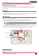
5 The rapid shutdown cables have a resistor connected to one end (on the red cable). Connect these ends to the switch,
making sure that the red and black cables are reversed relative to the cables connected at the top of the switch (going into
the DC side conduit between the inverter and the Safety Switch), as detailed below. Apply a torque of 2 N*m (18 lb*in):
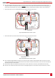
If the cables at the top are red and black from left to right, connect as shown below.
Figure 2: Rapid shutdown cable connected – option 1
If the cables at the top are black and red from left to right, connect as shown below.
Figure 3: Rapid shutdown cable connected – option 2
6 Use a standard straight-bladed screwdriver to connect the other end of the rapid shutdown cables to the DC connection
spring-clamp terminals: Connect the black cable from the switch to the DC- terminal block, and connect the red cable from
the switch to the DC+ terminal block.
7 Check that the cables are located and connected in the correct positions to ensure the rapid shutdown functionality.
8 Close the cover: Attach the switch cover and secure it by tightening the four screws with a torque of 0.9 ft.*lb / 1.2 N*m.
Red (+) Black (-)
Black (-)
DC+ DC-
Red (+) with rapid
shutdown resistor
Black (-) Red (+)
Black (-)
Red (+) with rapid
shutdown resistor
DC+ DC-