Disclaimers Disclaimers Important Notice Copyright © SolarEdge Inc. All rights reserved. No part of this document may be reproduced, stored in a retrieval system, or transmitted, in any form or by any means, electronic, mechanical, photographic, magnetic or otherwise, without the prior written permission of SolarEdge Inc. This document is solely for the use of SolarEdge customers and employees. The material furnished in this document is believed to be accurate and reliable.
Disclaimers FCC Compliance This equipment has been tested and found to comply with the limits for a Class B digital device, pursuant to part 15 of the FCC Rules. These limits are designed to provide reasonable protection against harmful interference in a residential installation. This equipment generates, uses and can radiate radio frequency energy and, if not installed and used in accordance with the instructions, may cause harmful interference to radio communications.
Table of Contents Table of Contents Disclaimers .......................................................................... 1 Important Notice ............................................................. 1 FCC Compliance ............................................................... 2 Table of Contents ................................................................ 3 About This Guide ................................................................. 5 Support and Contact Information ......................
Table of Contents Appendix B: Configuring the Home Gateway ..................... 22 Connecting to the Home Gateway via the SolarEdge Configuration Tool ......................................................... 23 Disabling the DHCP and Configuring the IP Settings ...... 25 Appendix C: Technical Specifications ................................. 26 4 Home Gateway Installation Guide – MAN-01-00118-1.
About This Guide About This Guide This user guide is intended for Photovoltaic (PV) system owners, installers, technicians, maintainers, and integrators who use the SolarEdge power harvesting system. This manual describes how to install and set up ZigBee™ communication between a SolarEdge device (inverters or Safety and Monitoring Interface) and the SolarEdge home gateway (also referred to as SolarEdge gateway). The manual instructions and graphics refer to the inverter; however apply to SMI as well.
About This Guide Appendix C: Technical Specifications, page 26, provides the electrical and mechanical specifications of the SolarEdge home gateway device. For further information, datasheets and the most up-to-date certifications for various products in different countries, please visit the SolarEdge website: www.solaredge.com 6 Home Gateway Installation Guide – MAN-01-00118-1.
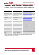
Support and Contact Information Support and Contact Information If you have technical queries concerning our products, please contact us: US & Canada 1877 360 5292 support@solaredge.us Germany +49 89-45459730 support@solaredge.de France 0800917410 support@solaredge.fr Belgium 080073041 support@solaredge.be Italy 800 784 824 support@solaredge.
Chapter 1: Introducing the Home Gateway Chapter 1: Introducing the Home Gateway Overview The SolarEdge home gateway is used for wireless connectivity between one or more inverters at a site and a remote internet gateway point. Wireless connectivity allows simplifying the installations as no outdoor cabling is required. The SolarEdge home gateway communicates using ZigBee, a standard for low-rate, highreliability, and multi device wireless protocol for telemetry communications.
Chapter 1: Introducing the Home Gateway Figure 2 shows an inverter as an example; however, this illustration is applicable to other SolarEdge devices, such as Safety and Monitoring Interface (SMI). Figure 2: Connection to the SolarEdge Inverter The home gateway is provided with one slave unit that is installed inside the inverter. Up to 15 SolarEdge inverters can be supported per one ZigBee wireless link. In order to enable more than one inverter, additional slave kits are required (sold separately).
Chapter 1: Introducing the Home Gateway Package Contents Home gateway with antenna This installation guide Power supply CAT 5E Ethernet cable ZigBee slave kit, including: ZigBee slave module Antenna with RF cable Mounting bracket clip for installing the antenna on the inverter Installation guide Installation Procedure The following illustrates the steps required for the home gateway installation: Install a slave module in all inverters and other SolarEdge devices Connect the home
Chapter 2: Home Gateway User Interfaces Chapter 2: Home Gateway User Interfaces Antenna Link LED (Yellow) S_OK LED (Green) Configuration Button Signal strength LEDs (x3, Green) USB Port Power LED (Green) Ethernet Port DIP Switches Figure 4: SolarEdge Home Gateway Interfaces Home Gateway Installation Guide – MAN-01-00118-1.
Chapter 2: Home Gateway User Interfaces Connectors USB: Connection to the power supply. This port can also be used for connecting to a computer for advanced configuration or SW upgrade. Ethernet: Connecting the SolarEdge gateway to the SolarEdge monitoring portal through an Ethernet switch/router. The Ethernet switch/router should be connected to the Internet. DIP Switches Two DIP switches are located at the side of the gateway.
Chapter 2: Home Gateway User Interfaces LEDs The gateway has four LED indicators, as follows: 1 Label and Color Indication Functionality S_OK (green) Connection with the SolarEdge monitoring portal ON - Connection with SolarEdge monitoring portal is OK OFF - Communication with the SolarEdge monitoring portal failed Link (yellow) Communication with associated slave(s) Blinking - There has been ZigBee communication in the last 15 minutes.
Chapter 3: Installing the SolarEdge Home Gateway Chapter 3: Installing the SolarEdge Home Gateway Installation Guidelines The following requirements apply when locating and mounting the SolarEdge gateway: The SolarEdge home gateway is suitable for mounting indoors only. For outdoor installation, use an external plastic outdoor enclosure (not provided by SolarEdge) The SolarEdge home gateway must always remain in an ambient temperature of -20°C (-4°F) to +60°C (140°F).
Chapter 3: Installing the SolarEdge Home Gateway Ensure that the antenna is always vertically oriented. Figure 6: Antenna Orientation Home Gateway Installation Guide – MAN-01-00118-1.
Chapter 3: Installing the SolarEdge Home Gateway Connecting the SolarEdge Gateway 1 Install the supplied ZigBee slave module in the slave device (inverters or SMI) as described in the ZigBee Slave Kit Installation Guide. To connect more slaves, purchase an additional ZigBee slave kit for each slave device (sold separately). 2 Connect the power supply to the USB connector and connect to an AC source. The power LED is lit to indicate power connection.
Chapter 3: Installing the SolarEdge Home Gateway Verifying the Connection 1 Verify that the S_OK LED is ON, which indicates the communication with the SolarEdge portal is established. This may take up to five minutes. If the LED does not light up, refer to Appendix A: Troubleshooting on page 18. 2 After device discovery, verify that the yellow (Link) LED blinks and indicates the correct amount of slaves, as described in the following illustration. One slave ON OFF 0.5 sec. 0.5 sec. |Pause| 5 sec. 0.
Appendix A: Troubleshooting Appendix A: Troubleshooting Troubleshooting Ethernet Connection If the S_OK LED on the gateway is not ON, use the diagnostics mode to identify the error: Press the gateway configuration button for more than 10 seconds and release it (after all LED turn on and then off while pressing). The home gateway is now in diagnostics mode. If all LEDs light up – no error has occurred. If one of the LEDs is OFF, refer to the following table to diagnose the problem.
Appendix A: Troubleshooting Label and Color Indication when OFF During diagnostic mode Troubleshooting RSSI 1 (Low, green) An Ethernet physical cable connection fault: The Ethernet link or physical Ethernet cable are not connected properly Check the cable pinout assignment and cable connection Link (yellow) The connection to the Internet is not available: Ping to google.com failed Connect a laptop and use the configuration tool to check for internet connection.
Appendix A: Troubleshooting Troubleshooting ZigBee Wireless Connection Yellow LED (Link) does not blink after device discovery If the yellow LED (Link) does not blink after device discovery, a connection error may have occurred. Try the following troubleshooting actions: Relocate the home gateway closer to the inverter to improve signal strength.
Appendix A: Troubleshooting b. 2 Check that S_OK appears in the Server field to indicate a functioning connection to the SolarEdge monitoring portal, which was validated during the last two minutes. Check that the appears in the Status field. If S_OK is not displayed, or Gateway Not Found / Master Not Found appear, then this is the slave not detected.
Appendix B: Configuring the Home Gateway Appendix B: Configuring the Home Gateway This procedure describes how to configure the home gateway to work with a static IP instead of automatic DHCP. When using standard automatic DHCP routers, this step is not required. Change the IP settings only when the router/server is set to static IP mode and as part of troubleshooting the Ethernet (Troubleshooting Ethernet Connection on page 18).
Appendix B: Configuring the Home Gateway Connecting to the Home Gateway via the SolarEdge Configuration Tool 1 Download and install the configuration tool as described in its manual. 2 Disconnect the home gateway from the AC source and connect it using a USB cable to the PC/laptop that has the configuration tool installed. 3 Double-click on the configuration tool icon. The SolarEdge configuration tool main window is displayed (with the Connect to SolarEdge product window).
Appendix B: Configuring the Home Gateway 4 If the Connect to SolarEdge product window does not appear at startup, click Connect in the main window. 5 In the Connect to SolarEdge product window, select the correct COM and click Connect. The home gateway configuration can now be viewed and edited, using the four buttons at the bottom-right of the screen, or the LCD button at the bottom left.
Appendix B: Configuring the Home Gateway Disabling the DHCP and Configuring the IP Settings 1 Use the up and down arrows to scroll to the Communication menu. Press Enter to select is. The following menu is displayed: S L R Z R 2 e A S i S r N 4 g 2 v e C 8 5 B e 3 2 r < L A N > o n f – 1 C o n f < S > e C o n f < S > C o n f Select LAN Conf.
Appendix C: Technical Specifications Appendix C: Technical Specifications North America Worldwide Unit 10 dBm Functional Number of inverters that can be monitored 1-15 Performance Transmit power 18 Receiver Sensitivity -102 EIRP with Antenna Outdoor (LOS) range 22 1 Indoor range* dBm 14 dBm 250 m 15 m Environmental Operating temperature Storage temperature Relative humidity (non condensing) Ingress protection -20 ÷ +60 °C -20 ° ÷ +60° °C 0 ÷ 80 % IP20 Power Supply Requirements