
Installation Manual
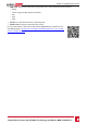
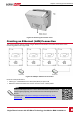
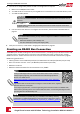

RJ45 Pin #
Wire Color
1
10Base-T Signal
100Base-TX Signal
T568B T568A
7 White/Brown White/Brown Reserved
8 Brown Brown Reserved
Figure 26: Standard cable wiring
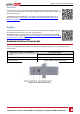
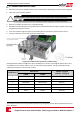
7. Useapre-crimpedcabletoconnectviagland#1totheRJ45plugontheinverter'scommunication
boardor,ifusingaspoolofcable,connectasfollows:
a. Insertthecablethroughthegland.
b. Removethecable’sexternalinsulationusingacrimpingtoolorcablecutterandexposeeight
wires.
c. InserttheeightwiresintoanRJ45connector,asdescribedinFigure26
d. Useacrimpingtooltocrimptheconnector.
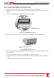
e. ConnecttheEthernetconnectortotheRJ45portonthecommunicationboard.
Figure 27: The RJ45 Ethernet connection
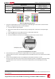
8. Fortheswitch/routerside,useapre-crimpedcableoruseacrimpertoprepareanRJ45
communicationconnector:InserttheeightwiresintotheRJ45connectorinthesameorderasabove
(Figure26).
9. ConnectthecableRJ45connectortotheRJ45portoftheEthernetswitchorrouter.
Youcanconnectmorethanoneinvertertothesameswitch/routerortodifferentswitches/routers,
asneeded.EachinvertersendsitsmonitoreddataindependentlytotheSolarEdgemonitoring
platform.
1
The inverter connection does not support RX/TX polarity change. Supporting crossover Ethernet cables depends on the
switch capabilities.
Chapter 6: Setting Up Communication
Single Phase Inverter with HD-Wave Technology Installation MAN-01-00306-1.1
57