
Installation Manual
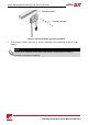
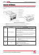
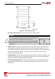

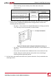

Figure 11: Inverter front view
l AC and DC conduit entries:ConnectionpointsoftheSafetySwitch.
CAUTION!
Do not remove the six screws on the DC conduit metal panel as it
may harm the inverter sealing and void the warranty.
Ces vis ne doivent pas être retirées. Les enlever est susceptible
d’endommager l’étanchéité de l’onduleur et annuler la validité de
la garantie.
l ON/OFF switch:TurningthisswitchONstartstheoperationofthepoweroptimizers,
enablespowerproductionandallowstheinvertertobeginexportingpowertothe
utilitygrid.TurningitOFFreducesthepoweroptimizervoltagetoalowsafetyvoltage
andinhibitsexportationofpower.WhenthisswitchisOFF,theinvertercontrol
circuitryremainspoweredup.
l LCD light button:PressingthisbuttonlightsuptheLCDfor30seconds.Inaddition,you
canpressthisbuttontoaccessconfigurationmenuoptions,asdescribedConfiguring
the Inverter Using the LCD Light Buttononpage55.
l Two communication glands,forconnectionofinvertercommunicationoptions.Each
glandhasthreeopenings.RefertoSetting Up Communicationonpage71formore
information.
SolarEdge-Installation Guide MAN-01-00002-4.0
26
Inverter Interfaces