
Installation Manual

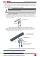
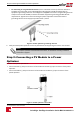

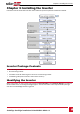
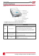
Table Of Contents
- Disclaimers
- Contents
- HANDLING AND SAFETY INSTRUCTIONS
- Chapter 1: Overview
- Chapter 2: Installing the Power Optimizers
- Chapter 3: Installing the Inverter
- Chapter 4: Auto-transformer and Backed-up Loads Panel Installation (for Backup Only)
- Chapter 5: Electricity Meter Installation
- Chapter 6: StorEdge Inverter Connections
- Chapter 7: User Interface
- Chapter 8: Commissioning the Installation
- Chapter 9: System Configuration
- Chapter 10: Setting Up Communication to the Monitoring Portal
- Appendix A: Troubleshooting
- Appendix B: Replacing and Adding System Components

AllLEDsturnonwhiletheinverterisbeingconfigured.
Figure 8: Inverter front view
l AC and DC conduit entries:ConnectionpointsoftheStorEdgeConnectionUnit.
l ON/OFF switch:TurningthisswitchONstartstheoperationofthepoweroptimizers,enablespower
productionandallowstheinvertertobeginexportingpowertotheutilitygrid/backed-uploads.
TurningitOFFreducesthepoweroptimizervoltagetoalowsafetyvoltageandinhibitsexportationof
power.WhenthisswitchisOFF,theinvertercontrolcircuitryremainspoweredup.
l LCD light button:PressingthisbuttonlightsuptheLCDfor30seconds.Inaddition,youcanpress
thisbuttontoaccessconfigurationmenuoptions,asdescribedConfiguringtheInverterUsingtheLCD
LightButtononpage43.
l Two communication glands,forconnectionofinvertercommunicationoptions.Eachglandhas
threeopenings.RefertoSettingUpCommunicationtotheMonitoringPortalonpage71formore
information.
StorEdge Connection Unit Interfaces
ThefollowingcomponentsarepartoftheStorEdgeConnectionUnitandmaybeaccessedfor
troubleshootingormaintenance.
Figure 9: StorEdge Connection Unit
Chapter 3: Installing the Inverter
SolarEdge-StorEdge Installation Guide MAN-01-00262-1.0
19