
Installation Manual
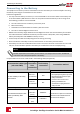
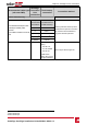


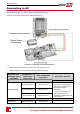
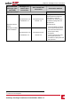
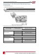
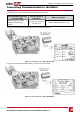
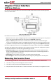
Table Of Contents
- Disclaimers
- Contents
- HANDLING AND SAFETY INSTRUCTIONS
- Chapter 1: Overview
- Chapter 2: Installing the Power Optimizers
- Chapter 3: Installing the Inverter
- Chapter 4: Auto-transformer and Backed-up Loads Panel Installation (for Backup Only)
- Chapter 5: Electricity Meter Installation
- Chapter 6: StorEdge Inverter Connections
- Chapter 7: User Interface
- Chapter 8: Commissioning the Installation
- Chapter 9: System Configuration
- Chapter 10: Setting Up Communication to the Monitoring Portal
- Appendix A: Troubleshooting
- Appendix B: Replacing and Adding System Components

Connecting to the Grid and to Backed-up Loads
Thissectiondescribes:
l ConnectiontotheACGrid.
l Connectionbetweentheinvertertothebacked-uploadspanel.
NOTE
Each inverter should be connected to a separate backup panel. Do not share backup output between
inverters.
Figure 22: Connection to grid, backed-up loads
Preparecablesandconnectasdescribedinthefollowingtable:
Recommended cable type
(min-max AWG)
StorEdge Connection
Unit connection
External connection
Grid
6 AWG (4-20 AWG)
3-pin terminal block: Grid L1 Main distribution panel: L1
3-pin terminal block: Grid L2 Main distribution panel: L2
3-pin terminal block: Grid N Main distribution panel: N
Min. 10 AWG grounding wire to ground
Backed-up loads panel
6 AWG (4-20 AWG)
3-pin terminal block: L1 Backed-up loads panel: L1
3-pin terminal block: L2 Backed-up loads panel: L2
3-pin terminal block: N Backed-up loads panel: N
Min. 10 AWG grounding wire to ground
SolarEdge-StorEdge Installation Guide MAN-01-00262-1.0
36
Connecting to the Grid and to Backed-up Loads