
StorEdge Connection & Configuration Guide


Backup Power with Smart Energy Management - System Configurations
6
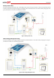
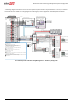
For configurations with more than one SolarEdge inverter, the inverters are connected to each other with RS485, with one
inverter configured as the master and connected to the SolarEdge monitoring server. An RS485 Expansion Kit is installed in the
inverter for connection of the meter on a second RS485 bus.
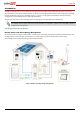
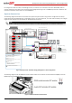
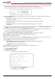
System Connection
The following diagram illustrates the connection of the system components when using the basic configuration for backup
power with Smart Energy Management: one StorEdge inverter, one auto-transformer, one meter and one battery. For enlarged
segments of this diagram, refer to Appendix D – Detailed System Connection.
NOTE
Install the GFDI (Ground-Fault Detector Interrupter) in accordance with applicable local standards and directives.
Figure 4: Backup Power with Smart Energy Management - Basic Configuration
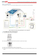
The following diagram shows the RS485 termination switch location on the inverter communication board (SW7) and on the
RS485 Expansion Kit (RS485 module).
Figure 5: RS485 termination switch location
L1 L2
Main
Distribution
Panel
CT
CT
CB
CB
15A CB
40A CB
CB
40A CB
Neutral
bus-bar
L1_Grid
N_Grid
L2_Grid
20A
CB
20A
CB
20A
CB
20A
CB
Backed-up Loads Distribution Panel
BU_L1
BU_L2
Connection to utility meter
25A
CB
25A
CB
BU_N
L1
N
L2
1" Conduit
Backup Neutral bus-bar
3
Meter AC [L1, L2, N], 12 -16 AWG
8 ft twisted pair supplied with the CT
Meter is required only for Smart Energy Managment
RS485 [A,B,G], 24 AWG (16-24 AWG),
Shielded twisted pair, 600V insulated
3
Inverter AC Grid [L1, L2, N], 6 AWG (4-20 AWG)
3
3
Inverter AC Backup [L1, L2, N], 6 AWG (4-20 AWG)
Backup
Panel Main
Breaker
Backed-up Loads
Breakers
Type B for main circuit breakers
Battery HV DC+, 10 AWG (8-12 AWG), 600V insulated
Battery HV DC- , 10 AWG (8-12 AWG), 600V insulated
+
-
V+
V-
2
Thermal [V+, V-], 16AWG (12-16 AWG),
Shielded pair, 600V insulated
PWRV+
G
5
Control [V+, G, En, A+, B-], 24AWG (16-24 AWG),
Shielded twisted pairs, 600V insulated
RTN
En
A+
B-
EN
P
N
Auto-
transformer
3/4" Conduit
3/4" Conduit
L1_A.T.
N_A.T.
L2_A.T.
T1
T2
L1_A.T.
N_A.T.
L2_A.T.
T1
T2
Auto-transformer AC [L1, L2, N], 8 AWG (6-20 AWG)
3
2
Temp. sense [T1, T2], 24 AWG (16-24 AWG),
600V insulated
RS485
SolarEdge
Meter
A -
B+
G
N
ØL1
ØL2
ØL3
L1 CT
L2 CT
L3 CT
Main Breaker
To the backed-up loads
3/4" Conduit
PV DC+, 10 AWG (4-20 AWG), 600V insulated
PV DC- , 10 AWG (4-20 AWG), 600V insulated
2
2
StorEdge
Inverter
BAT
IN
Fuses
12A
CB
CB
CBCB
CBCB
CB
CB
CB
CB
CB
CB
15A CB
CB
Notes
Note 1: Recommended Fuses in StorEdge Inverter:
12A 600VDC Quick-Acting, 10 x 38 mm Solar Midget Fuses
(Example: Littelfuse P/N 0SPF012)
Note 2: Auto-transformer connection:
6ft max
Vertical mounting only (conduit connection from the bottom)
Use 10 AWG wire for grounding
Note 3: Battery connection:
35ft max
Distance larger than 5ft requires installation of external DC
safety switch on the battery side
Control [B-,A+] must be twisted pair
Note 4: Install type B 2-pole 25A main circuit breaker to ensure the
25A phase limit imbalance is maintained at all times.
Notes 1
Notes 2
Notes 3
L1_BU
L2_BU
N_BU
RS485-1 Terminations
Move up the left switch
Notes 4
1/2" Conduit
3/4" Conduit
Battery
Battery switches settings:
RS485