Installation Guide Three Phase Inverters with Synergy Technology PN:SExxK-xxxxIxxxx For North America Version 1.
Disclaimers Disclaimers Important Notice Copyright © SolarEdge Inc. All rights reserved. No part of this document may be reproduced, stored in a retrieval system or transmitted, in any form or by any means, electronic, mechanical, photographic, magnetic or otherwise, without the prior written permission of SolarEdge Inc. The material furnished in this document is believed to be accurate and reliable. However, SolarEdge assumes no responsibility for the use of this material.
2 FCC Compliance FCC Compliance This equipment has been tested and found to comply with the limits for a Class A digital device, pursuant to part 15 of the FCC Rules. These limits are designed to provide reasonable protection against harmful interference. This equipment generates, uses and can radiate radio frequency energy and, if not installed and used in accordance with the instructions, may cause harmful interference to radio communications.
Revision History 3 Revision History Version 1.1 (Feb. 2022) Change in connection method of DC wires to a Synergy Manager with DC wire terminals and updated Rapid Shutdown (PVRSS) initiation. Added mounting brackets dimension drawings. Version 1.
4 Revision History Contents Disclaimers Important Notice FCC Compliance 1 1 2 Revision History 3 HANDLING AND SAFETY INSTRUCTIONS Safety Symbols Information 6 6 IMPORTANT SAFETY INSTRUCTIONS / CONSIGNES DE SÉCURITÉ IMPORTANTES 7 Photovoltaic Rapid Shutdown System Requirements 11 Photovoltaic Hazard Control Application 13 Chapter 1: Introducing the SolarEdge Power Harvesting System Power Optimizer Three Phase Inverter with Synergy Technology Monitoring Platform Designer Installation Tools and Ma
Revision History 5 Connecting PV Strings to the Synergy Manager Connecting PV Arrays to the Synergy Manager Connecting Ground and AC Wires to the Synergy Manager 46 48 50 Chapter 5: Activating, Commissioning and Configuring the System On-grid Commissioning of the inverter Step 1: Activating the Installation Step 2: Commissioning and Configuring the Installation Step 3: Verifying Proper Activation and Commissioning Pre-commissioning (Off-Grid) Reporting and Monitoring Installation Data Signaling Options
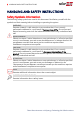
6 HANDLING AND SAFETY INSTRUCTIONS HANDLING AND SAFETY INSTRUCTIONS Safety Symbols Information The following safety symbols are used in this document. Familiarize yourself with the symbols and their meaning before installing or operating the system. WARNING! Denotes a hazard. It calls attention to a procedure that, if not correctly performed or adhered to, could result in injury or loss of life. Do not proceed beyond a warning note until the indicated conditions are fully understood and met.
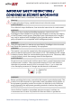
IMPORTANT SAFETY INSTRUCTIONS / CONSIGNES DE SÉCURITÉ IMPORTANTES 7 IMPORTANT SAFETY INSTRUCTIONS / CONSIGNES DE SÉCURITÉ IMPORTANTES SAVE THESE INSTRUCTIONS / CONSERVEZ CES INSTRUCTIONS Warning! To reduce the risk of injury, read all instructions in this document. AVERTISSEMENT! Pour réduire le risque de blessure, lisez toutes les instructions de ce document.
8 IMPORTANT SAFETY INSTRUCTIONS / CONSIGNES DE SÉCURITÉ IMPORTANTES câblage fixe, métallique, l'équipement-le conducteur de mise à la terre doit être exécuté avec les conducteurs de circuit et raccordé à l'équipement borne de mise à la terre ou de plomb sur le produit. WARNING! Opening the inverter and repairing or testing under power must be performed only by qualified service personnel familiar with this inverter.
IMPORTANT SAFETY INSTRUCTIONS / CONSIGNES DE SÉCURITÉ IMPORTANTES 9 WARNING! SafeDC complies with IEC60947-3 when installing the system with a worst case SafeDC voltage (under fault conditions) < 120V.
10 IMPORTANT SAFETY INSTRUCTIONS / CONSIGNES DE SÉCURITÉ IMPORTANTES NOTE SolarEdge inverters can be installed in sites with an alternative power source such as a generator. SolarEdge requires installing a physical or electronic interlock, which will signal to the inverter when the grid has been disconnected. Interlock procurement, installation, maintenance and support are the responsibility of the installer.
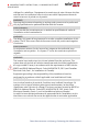
Photovoltaic Rapid Shutdown System Requirements 11 Photovoltaic Rapid Shutdown System Requirements This section is applicable to all Three Phase Inverters with Synergy Technology having Synergy Units marked with “R” in the part numbers: SESUK-USRxxxxx. WARNING! THIS PHOTOVOLTAIC RAPID SHUTDOWN SYSTEM (PVRSS) INCORPORATES ONE OR MORE PIECES OF EQUIPMENT THAT EXERCISE THE RAPID SHUTDOWN CONTROL OF PV SYSTEM CONDUCTORS REQUIRED BY SECTION 690.12 OF THE NEC (NFPA 70).
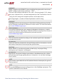
12 Photovoltaic Rapid Shutdown System Requirements (2) A rapid shutdown switch shall have a label located on or no more than 3 ft from the switch that includes this wording. The label shall be reflective, with all letters capitalized and having a minimum height of 3/8 in., in white on red background.
Photovoltaic Hazard Control Application 13 Photovoltaic Hazard Control Application SolarEdge commercial optimizers and inverters have been evaluated and listed to UL 3741 and may be used to form a PV hazard control system that utilizes SolarEdges PV rapid shutdown system to comply with NEC 690.12. Multiple modules may be connected in series to the optimizer input without exceeding the input voltage rating of the optimizer (125V dc).
14 Photovoltaic Hazard Control Application WARNING! Upon servicing replacing equipment, instructions in this installation guide must be followed to maintain the integrity of the PV hazard control system. SolarEdge commercial optimizers and three phase inverters should only be replaced with SolarEdge commercial optimizers and inverters. Third party equipment is not compatible.
Chapter 1: Introducing the SolarEdge Power Harvesting System 15 Chapter 1: Introducing the SolarEdge Power Harvesting System The SolarEdge power harvesting solution is designed to maximize the power output from any type of solar Photovoltaic (PV) installation while reducing the average cost per Watt. Figure 1 shows and the following sections describe the components of the SolarEdge power harvesting system.
16 Three Phase Inverter with Synergy Technology During fault conditions The Power Optimizers are disconnected from the inverter The inverter ON/OFF/P switch is turned OFF The safety Voltage mechanism of the Power Optimizers also serves as part of a Photovoltaic Rapid Shutdown System (PVRSS). PVRSS, enable firefighters to reduce the Voltage and current of a PV strings to protect themselves from electrical hazards during fire.
Chapter 1: Introducing the SolarEdge Power Harvesting System 17 Figure 2: Synergy Manager with three Synergy Units Monitoring Platform The monitoring platform enables monitoring the technical and financial performance of one or more SolarEdge sites. It provides past and online information on the system performance, both at the system and PV module levels. Designer Designer recommends inverter and Power Optimizer selection per site size and enables report generation.
18 Installation Procedure Ring terminals crimping tool Wire cutters Wire strippers Voltmeter For installing the communication options, you may also need the following: For Ethernet: CAT6 twisted pair Ethernet cable with RJ45 connector If using a CAT6 cable spool: RJ45 plug and RJ45 crimper For RS485 / CAN Bus : Four- or six-wire shielded twisted pair cable Watchmaker precision screwdriver set Installation Procedure The following procedures, are required for installing and setting up a new SolarEdge site.
Chapter 2: Installing the Power Optimizers 19 Chapter 2: Installing the Power Optimizers Safety The following notes and warnings apply when installing the SolarEdge Power Optimizers. Some of the following may not be applicable to smart modules: WARNING! The metallic enclosure of the Power Optimizer must be grounded in accordance with the product's listing and local and national codes.
20 Safety CAUTION! All PV modules must be connected to a Power Optimizer. ATTENTION! Tous les modules doivent être connectés à un optimiseur de puissance. CAUTION! If you intend to mount the Power Optimizers directly to the module or module frame, first consult the module manufacturer for guidance regarding the mounting location and the impact, if any, on module warranty. Drilling holes in the module frame should be done according to the module manufacturer instructions.
Chapter 2: Installing the Power Optimizers 21 ATTENTION! Les connecteurs du module doivent être mécaniquement compatibles avec les optimiseurs de puissance. Sinon, le système SolarEdge installé peut être dangereux ou causer des problèmes fonctionnels, tels que les défauts de terre, qui peuvent provoquer un arrêt de l’onduleur. Afin d'assurer la compatibilité mécanique entre les optimiseurs de puissance SolarEdge et les modules auxquels ils sont connectés:.
22 Installation Guidelines P-Series Power Optimizers with the 4-type suffix in their part number (Pxxx4xxxxxx) and the Mxxxx-Series - extension cables of up to 52 ft / 16 m can be installed per Power Optimizer (26 ft / 8 m for DC+, and 26 ft / 8 m for DC-). Between two Power Optimizers or between a Power Optimizer and the inverter: Extension cables can be installed between Power Optimizers only from row to row, around obstacles or pathways within a row and from the end of the PV string to the inverter.
Chapter 2: Installing the Power Optimizers 23 Completely shaded modules may cause their Power Optimizers to temporarily shut down. This will not affect the performance of the other Power Optimizers in the PV string, as long as the minimum number of unshaded Power Optimizers connected in a PV string of modules is met. If under typical conditions fewer than the minimum Power Optimizers are connected to unshaded modules, add more Power Optimizers to the PV string.
24 Step 1: Mounting and Grounding the Power Optimizers Step 1: Mounting and Grounding the Power Optimizers (1) For each of the Power Optimizers : 1. Determine the Power Optimizer mounting location and use the Power Optimizer mounting brackets to attach the Power Optimizer to the support structure (See Figure 3). It is recommended to mount the Power Optimizer in a location protected from direct sunlight.
Chapter 2: Installing the Power Optimizers (1) 4. Use the following methods 25 to ground the Power Optimizer: WARNING! The metallic enclosure of the Power Optimizer must be grounded in accordance with the requirements of the local and national codes. AVERTISSEMENT! L'enceinte métallique de l’optimiseur de puissance doit être mise à la terre en accord avec les régulations locales et nationales.
26 Step 1: Mounting and Grounding the Power Optimizers For mounting on rails with sliding nut fasteners: If the star washer cannot be used, use the SolarEdge grounding plate (purchased separately) between the railing and the flat side of the mounting bracket. Use mounting specific hardware as needed. Apply a torque of 9.5 N*m / 7 lb*ft. See Figure 4.
Chapter 2: Installing the Power Optimizers 27 5. Verify that each Power Optimizer is securely attached to the module support structure. 6. Record Power Optimizer serial numbers and locations, as described in Reporting and Monitoring Installation Data on page 61. Step 2: Connecting a PV module to a Power Optimizer NOTE Improper wiring may cause electrical faults in a PV system. To avoid electrical faults, verify proper locking of connectors and avoid cable tension and friction.
28 Step 3: Connecting Power Optimizers in PV strings Step 3: Connecting Power Optimizers in PV strings You can construct parallel PV strings of unequal length, that is, the number of Power Optimizers in each PV string does not have to be the same. The minimum and maximum PV string lengths are specified in the power datasheets. Refer to the SolarEdge Site Designer for PV string length verification.
Chapter 2: Installing the Power Optimizers 29 Step 4: Verifying Proper Power Optimizer Connection When a module is connected to a Power Optimizer, the Power Optimizer outputs a safe voltage of 1V (±0.1V). Therefore, the total PV string voltage should equal 1V times the number of Power Optimizers connected in series in the PV string. For example, if 10 Power Optimizers are connected in a PV string, then 10V should be produced. Make sure the PV modules are exposed to sunlight during this process.
Chapter 3: Installing the Synergy Manager and Synergy Units 30 Chapter 3: Installing the Synergy Manager and Synergy Units This section, describes how to install the inverter. Install the Synergy Manager and Synergy Unit either before or after the PV modules and Power Optimizers have been installed. The inverter is provided with a mounting template that ensures correct installation location of the Synergy Manager and all Synergy Unit mounting brackets.
31 Front Interface of Synergy Manager Front Interface of Synergy Manager Figure 8: Synergy Manager Unit - Front interfaces DC Disconnect Switch The DC Disconnect Switch is a manually operated safety switch for disconnecting the DC power of the SolarEdge system. NOTE When the Synergy Manager is OFF (for example during maintenance) it may be locked to prevent a safety hazard: 1. Move the switch to the Lock position. 2. Insert the lock through the knob opening and lock.
Chapter 3: Installing the Synergy Manager and Synergy Units 32 OFF (0) - Turning this switch OFF reduces the Power Optimizer Voltage to a low safety Voltage and inhibits exportation of power. When this switch is OFF, the Synergy Manager and Synergy Units control circuitry remains powered up. P - Holding the switch pressed in P position allows performing the following functions: P Position duration Function Comments Displays production information for 5 seconds on the SetApp screen.
33 Front Interface of Synergy Manager Indication LEDs (1) (2) LEDs indication consists on color and state (on/ off/ blinking / flickering /alternating (3) ). The LEDs indicate different system information, such as errors or performance. Figure 10 shows the Indication LEDs of the Synergy Manager. Generally, the main LED indications are: COMM.
Chapter 3: Installing the Synergy Manager and Synergy Units ON/ OFF/ P Indication switch position 34 LED Comment FAULT POWER COMM.
35 Inverter Interconnection Cable Interfaces Indication ON/ OFF/ P switch position Percentage of AC Production: 0 - 33 % Percentage of AC Production: 33 - 66 % Percentage of AC Production: 66 - 100 % ON (1) LED color Comment Red Green Blue OFF ON OFF OFF OFF ON OFF ON ON This indicates power production as percentage of rated peak AC output power Inverter Interconnection Cable Interfaces The cables on the right hand side of the Synergy Manager, interfaces the Synergy Manager to the Synergy
Chapter 3: Installing the Synergy Manager and Synergy Units 36 Synergy Manager External Cable Interface The conduit entries, at the bottom side of the Synergy Manager, interfaces the inverter to the grid and PV arrays. The communication glands, support communication cables connecting the inverter to the SolarEdge Monitoring platform and external power bank used for setting up the inverter in sites with no available grid power.
37 Drilling Conduit Holes AC connector: for supply of AC power to the Synergy Manager Figure 13: Synergy Unit Interface Connectors Drilling Conduit Holes This section describes how to drill AC and DC openings at the bottom of the Synergy Manager for connecting the AC and DC conduits. This procedure must be performed before mounting the Synergy Manager. To open conduit drill guides: 1. Ensure that the Safety Switch is set to OFF (0) and ON/OFF/P switch of the Synergy Manager is in OFF position. 2.
Chapter 3: Installing the Synergy Manager and Synergy Units 38 Figure 14: AC and DC panels with drill guides at the bottom of the Synergy Manager 3. Locate the drill guides for conduits on the DC and AC panels. Drill entry hole(s) for up to 2" conduit on the DC panel and 2.5" on the AC panel or drill entry hole for a single conduit, within the boundary marked on the inner side of the DC panel (see Figure 14 ). NOTE In some models, the DC panel has three drill entry hole(s) for up to 3" conduits. 4.
39 Mounting and Connecting the Synergy Manager and Synergy Units CAUTION! HEAVY OBJECT. To avoid muscle strain or back injury, use proper lifting techniques, and if required - a lifting aid. ATTENTION Objet lourd. Pour éviter la fatigue musculaire ou des blessures au dos, utilisez des techniques de levage appropriées et, si nécessaire - un auxiliaire de levage lors du retrait.
Chapter 3: Installing the Synergy Manager and Synergy Units 40 locations for the bracket of the Synergy Units (see pencil icons in Figure 15). Figure 15: Marking the drilling holes locations 4. Place the mounting templates vertically against the wall and mark the drilling hole locations for the bracket of the Synergy Manager. Make sure that the template aligns with the two drilling holes marked A. 5. Drill two holes for each bracket and mount the brackets. 6.
41 Mounting and Connecting the Synergy Manager and Synergy Units For the right or left Synergy Units, insert only one screw through the outer (exposed) side of the unit and into the bracket. Tighten the screws to a torque of 2.9 lb.*ft (see Figure 16 ). NOTE For the center Synergy Unit, use both side screws. Figure 16: Hanging the Synergy Unit 8. Hang the Synergy Manager: a. Lift the Synergy Manager from its sides. b.
Chapter 3: Installing the Synergy Manager and Synergy Units 42 Figure 17: Hanging the Synergy Manager Horizontal Mounting of the Inverter The inverter can be installed horizontally, on a flat surface, at any tilt above 10° (see Figure 18 ). The inverter can be installed under or near the PV modules, thus saving roof space and using the PV modules for shading the inverter. For more information on horizontal mounting, refer to Horizontal Mounting of Three Phase Inverters.
Chapter 4: Connecting PV Modules and AC to the Synergy Manager 43 Chapter 4: Connecting PV Modules and AC to the Synergy Manager This section describes how to connect the inverter to the PV modules and to the AC. Connecting PV Modules to the Synergy Manager The Synergy Manager is designed to directly connect up to 12 PV strings or up to three PV arrays via an external combiner box.
44 Connection Methods Figure 20: Connection of PV arrays to the Synergy Manager Connection of PV arrays to the Synergy Manager is performed via a combiner box. A combiner box is an electrical distribution box that my also host DC circuit breakers. The main purpose of the box is to combine multiple parallel strings of PV modules in the system into a single DC output. This DC output is then connected to a single input in the Synergy Manager of the inverter.
Chapter 4: Connecting PV Modules and AC to the Synergy Manager Figure 21 shows the various methods of connection of DC from the PV strings and PV arrays to Synergy Manager. Figure 21: Connecting methods of PV Strings and PV arrays to Synergy Manager NOTE SolarEdge fixed input Voltage architecture enables parallel PV strings to be of different lengths. Therefore, they do not need to have the same number of Power Optimizers as long as the length of each PV string is within the permitted range.
46 Connecting PV Strings to the Synergy Manager Connecting PV Strings to the Synergy Manager To connect the DC wires to a Synergy Manager with spring-clamp DC terminals: 1. Thread a 6 to 12 AWG wire through the AC conduit. 2. Strip 0.7" (18 mm) of wire insulation from the end of the wire. NOTE When using a stranded wire, use of ferrule is at the installer discretion 3. Insert the DC conduit into the DC-side opening at the bottom left-side of the Synergy Manager and fasten the conduit nut.
Chapter 4: Connecting PV Modules and AC to the Synergy Manager 47 c. Insert the wire into the top opening (see Figure 22). d. Remove the screwdriver – the wire is automatically clamped. CAUTION! Ensure that the Plus (+) wire is connected to the + terminal and that the Minus (-) wire is connected to the Minus (-) terminal connector. ATTENTION! Veillez à ce que le câble Plus (+) soit connecté au terminal + et que le câble - soit connecté au connecteur terminal. 6.
48 Connecting PV Arrays to the Synergy Manager Connecting PV Arrays to the Synergy Manager When connecting cables from a combiner box, ensure that the cable pairs of the PV arrays are marked with DC+ and DC- labels. To connect the PV arrays to a Synergy Manager with DC wire terminals: 1. Route the DC wires through the DC conduit. NOTE Use wires with 4 to 2 AWG cross section conductor. When using fine stranded wires, crimp ferrules on wires. 2.
Chapter 4: Connecting PV Modules and AC to the Synergy Manager 49 NOTE Before connecting aluminum wires to the terminals: a. Remove oxide from the exposed wires with emery paper or a steel wire brush b. Clean dust with a cloth and Isopropyl alcohol (IPA) c. Coat wires with a designated antioxidant aluminum wire grease immediately after cleaning 5. Route the DC wires to the DC+ and DC- terminals on the DC+ and DC- boards of the Synergy Manager (see DC+ and DC- labels on DC boards).
50 Connecting Ground and AC Wires to the Synergy Manager 7. Close the Synergy Manager cover and secure it by tightening the six screws to a torque of 2.6 ft.*lb. 8. Ensure proper conduit sealing; inspect the entire conduit run and use standard conduit sealants to avoid water penetration. Connecting Ground and AC Wires to the Synergy Manager This section describes how to connect AC and Ground (also referred to Protective Earth - PE) to the Synergy Manager.
Chapter 4: Connecting PV Modules and AC to the Synergy Manager 51 To connect Protective Earth (PE) to the Synergy Manager: 1. Turn OFF and secure the main AC circuit breaker in OFF position at the circuit breakers panel. 2. Release the six Allen screws and carefully remove the cover of the Synergy Manager. CAUTION! When removing the cover, make sure not to damage internal components. SolarEdge will not be held responsible for any components damaged as a result of incautious cover removal.
52 Connecting Ground and AC Wires to the Synergy Manager NOTE Before connecting lugs to aluminum wires: a. Remove oxide from the exposed wires with emery paper or a steel-wire brush b. Clean dust with a cloth and Isopropyl alcohol (IPA) c. Coat wires with a designated antioxidant aluminum wire grease immediately after cleaning NOTE Use ferrule when connecting a fine stranded wire. Figure 24: Connecting the Protective Earth (PE) wire NOTE Ground the conduit nut if required by regulation.
Chapter 4: Connecting PV Modules and AC to the Synergy Manager 53 Figure 25: Upper cover of AC terminal block 3. Route the AC wires through the AC conduit. 4. Fasten the conduit nut inside the Synergy Manager. NOTE Ground the conduit nut if required by regulation. 5. Strip the required length of insulation from the AC cable and AC wires. NOTE Before crimping lugs to aluminum wires: a. Remove oxide from the exposed wires with emery paper or a steel wire brush b.
54 Connecting Ground and AC Wires to the Synergy Manager Figure 26: Crimping a lug on an AC wire Lug parameters: Bolt hole diameter size: 0.5" Compression lugs of the one-hole, standard barrel, 600V type. Maximum wire size: 4/0 AWG 120 mm2 Maximum lug tongue thickness: 0.27 " Maximum lug tongue width: 1.29 " 7. Use heat shrink to isolate the lug barrels. 8. Remove the nut of the AC terminals. 9. Connect the lug of the AC wires according to the labels on AC terminal block.
Chapter 4: Connecting PV Modules and AC to the Synergy Manager 55 Figure 27: Connecting AC wires to the AC terminals 10. Place the upper cover of the AC terminal block and push until a lock click is heard. Close the Synergy Manager cover and secure it by tightening the six screws to a torque of lb*ft2.6.
56 Chapter 5: Activating, Commissioning and Configuring the System Chapter 5: Activating, Commissioning and Configuring the System After the solar system is installed, it is important to activate and commission the solar system. Activation and commission of the system is performed using the inverter SetApp mobile application.
Chapter 5: Activating, Commissioning and Configuring the System 57 On-grid Commissioning of the inIerter Step 1: Activating the Installation During system activation, a Wi-Fi connection is created between the mobile device and the inverter and the system firmware is upgraded. Before activation Download, register (first time only) and login to SetApp on your mobile device. Verify that the application is updated with the latest version.
58 Step 2: Commissioning and Configuring the Installation If the inverter has already been activated and commissioned: If not already ON - turn ON AC to the inverter by turning ON the circuit breaker on the main distribution panel. Open SetApp and follow the on-screen instructions (scan the inverter QR code, move the ON/OFF/P switch to P position for 2 seconds and release). The mobile device creates a Wi-Fi connection with the inverter and displays the main Commissioning screen.
Chapter 5: Activating, Commissioning and Configuring the System 59 When the inverter starts converting power after the initial connection to the AC, the inverter enters Wake up mode until its working voltage is reached. This mode is indicated by the flickering green inverter LED. When working voltage is reached, the inverter enters Production mode and produces power. The steadily lit green inverter LED indicates this mode. 4. Tap OK to return to the Commissioning menu.
60 Pre-commissioning (Off-Grid) Pre-commissioning (Off-Grid) The following items are required for Pre-commissioning: Mobile device with SolarEdge SetApp application Power bank: 60W output port, USB-C Power Delivery (PD): 20V 3A (not provided) USB cable: 3.3 ft (1 meter), USB-C to USB-C (not provided) IMPORTANT NOTE Commissioning should be performed in full daylight. NOTE When pre-commissioning multiple inverters, each inverter need to be commission individually. To pre-commission the inverter: 1.
Chapter 5: Activating, Commissioning and Configuring the System 61 Figure 28: Pre-commissioning the inverter 5. Start SetApp on your mobile device and follow the on-screen instructions. 6. When instructed, hold the ON/OFF/P Switch in P position and release within two seconds and continue to follow the on-screen instructions. 7. Disconnect the power bank and cover the power bank input port. 8. Turn-off the DC Disconnect Switch and the ON/OFF/P Switch. 9.
62 Reporting and Monitoring Installation Data Pinpoint the location of alerted components using the physical layout. The monitoring platform enables accessing site information, including up-to-date information viewed in a physical or logical view: Logical Layout: Shows a schematic tree-layout of the components in the system, such as: inverters, Power Optimizers, PV arrays, modules, meters and sensors, as well as their electrical connectivity.
Chapter 5: Activating, Commissioning and Configuring the System 63 Physical Layout Editor 1. If you are a registered installer, access the monitoring platform site creation page at https://monitoring.solaredge.com/solaredgeweb/p/home#createSites. If you have not yet signed up, go to https://monitoring.solaredge.com/solaredgeweb/p/createSelfNewInstaller. 2.
64 Signaling Options Figure 29: Example of Alternative Power Source System The Power reduction Interface (PRI) terminal block on the communication board (See Figure 30 ) is used signaling the inverter to switch to Alternative Power Source mode. Figure 30: PRI Terminal Block Location on the Communication Board of the Inverter For detailed connection and configuration of the inverter in alternative power source mode, refer to: https://www.solaredge.
Appendix A: Errors and Troubleshooting 65 Appendix A: Errors and Troubleshooting This chapter describes how to troubleshoot general system problems. For further assistance, contact SolarEdge Support. Identifying Errors Errors may be indicated in various system interfaces: On the inverter bottom panel, a red LED indicates an error. In the monitoring platform and SetApp, errors are displayed with codes. For more information on the codes displayed for error and warning messages, refer to https://www.
66 Power Optimizer Troubleshooting Power Optimizer Troubleshooting Malfunction Possible Cause and Corrective Action Power Optimizers are shaded. If you connected the inverter to the monitoring platform, retry pairing remotely (during sunlight). Make sure to leave the inverter ON/OFF/P switch ON and that S_OK appears in the status screen. Pairing failed Power Optimizer (s) output is disconnected. PV string Voltage is 0V Connect all Power Optimizer outputs.
Appendix A: Errors and Troubleshooting Malfunction 67 Possible Cause and Corrective Action Extra Power Optimizer(s) connected in the PV string (not applicable to smart modules). Check if an extra Power Optimizer is connected in the PV string. If not – proceed to next solution. PV string Voltage is higher than number of Power Optimizers WARNING! If the measured voltage is too high, the installation may not have a safe low voltage. PROCEED WITH CARE! A deviation of ±1% per PV string is reasonable.
68 Troubleshooting Communication Troubleshooting Communication Troubleshooting Ethernet (LAN) Communication The possible errors and their troubleshooting are detailed in the following table: Error Message Possible Cause and Troubleshooting Physical connection fault. Check the cable pinout assignment and cable connection. LAN cable disconnected No DHCP Configure Static IP or set to DHCP Gateway not responding No Internet connection IP settings issue. Check the router and configuration.
Appendix A: Errors and Troubleshooting 69 Additional Troubleshooting 1. Check that the modem or hub/router is functioning properly. 2. Check that the connection to the internal connector on the communication board is properly done. 3. Check that the selected communication option is properly configured. 4. Use a method independent of the SolarEdge device to check whether the network and modem are operating properly. For example, connect a laptop to the Ethernet router and connect to the Internet. 5.
70 Appendix B: Adding Optional Components Appendix B: Adding Optional Components This appendix describes the optional components available for the inverter. Before ordering component, verify that your inverter model supports the component and that the component is not already provided with the inverter. Ordered Installation and replacement kits for components include procedures for removal and installation of the components.
Appendix B: Adding Optional Components 71 https://www.solaredge.com/sites/default/files/se-cellular-plug-in-for-inverters-withsetapp-installation-guide.
72 Appendix C: Mechanical Specifications Appendix C: Mechanical Specifications The following figure shows the dimensions of the Three Phase Inverter with Synergy Technology.
Appendix C: Mechanical Specifications Synergy Manager mounting bracket Synergy Unit mounting bracket Three Phase Inverters with Synergy Technology PN: SExxK-xxxxIxxxx 73