SolarEdge StorEdge Solution Applications Connection and Configuration Guide For North America Version 1.
Introduction StorEdgeTM Solution Applications – Connection and Configuration (North America) Contents Introduction ........................................................................................................................................................................... 2 StorEdge Operation Modes ........................................................................................................................................................ 2 Smart Energy Management Applications .....
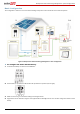
Introduction Introduction SolarEdge’s StorEdge Solution can be used for various applications that enable energy independence for system owners, by utilizing a battery to store power and supply power as needed. The StorEdge Solution is based on and managed by the StorEdge Inverter with Backup (referred to as “StorEdge inverter” or “inverter” throughout the document) for both PV and battery management, and is compatible with the Tesla Powerwall Battery.
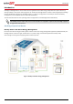
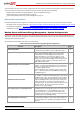
Introduction Backup Power Only Use stored energy for backup power only. The StorEdge inverter monitors the grid, and when it is down it automatically switches to backup mode, disconnecting from the grid and supplying power to backed-up loads. In cases where battery charging from the grid is permitted, this mode can be used without PV modules. Figure 2: Backup power only Smart Energy Management Only Use stored energy for smart energy management applications (detailed below).
Introduction In addition to these three modes, the StorEdge inverter can be used without a battery as a PV inverter with no StorEdge applications. NOTE For configuring the inverter when not using any StorEdge applications, refer to Appendix E - StorEdge Inverter without a Battery. NOTE The StorEdge inverter requires CPU version 3.18xx and above. If an upgrade is required contact SolarEdge support for an upgrade file and instructions. All modes can be used together with the export limitation application.
Backup Power with Smart Energy Management - System Configurations The next chapters describe each of these configurations for each of the three modes described above, and the required system setup via the inverter LCD and internal buttons and via the monitoring portal (where applicable). Backup Power with Smart Energy Management - System Configurations, page 5. Backup Power Only - System Configurations, page 18. Smart Energy Management Only - System Configurations, page 27.
Backup Power with Smart Energy Management - System Configurations For configurations with more than one SolarEdge inverter, the inverters are connected to each other with RS485, with one inverter configured as the master and connected to the SolarEdge monitoring server. An RS485 Expansion Kit is installed in the inverter for connection of the meter on a second RS485 bus.
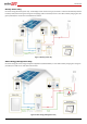
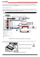
Backup Power with Smart Energy Management - System Configurations The following diagram illustrates the connection of the system components when using two batteries. In this case, an external fused combiner box is needed. For enlarged segments of this diagram, refer to Appendix D – Detailed System Connection.
Backup Power with Smart Energy Management - System Configurations Basic Configuration This configuration is based on one of each of the StorEdge components and is suitable for most residential systems.
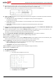
Backup Power with Smart Energy Management - System Configurations 5 Check the Communication status screen and verify that the battery and the meter are properly connected and configured: Prot – Displays how many devices are communicating with the inverter on the RS485-1 bus. ## – Displays how many devices are configured to communicate with the inverter on the RS485-1 bus. 6 If Dev is not MLT, the system is not pre-configured and requires full configuration. Proceed with step 9 below.
Backup Power with Smart Energy Management - System Configurations 2 To set a minimum battery charge level, so that the battery will always have energy stored in case backup power is needed, do the following: Select Power Control Energy Manager Storage Control. The following is displayed: 3 Select Backup RSVD and set the required level as percentage of the battery capacity. Set %PV according to user requirement.
Backup Power with Smart Energy Management - System Configurations 2 Select AC Charge Enable. 3 Select AC Charge Lim Limit Type and set one of the limits: 4 Set %PV to enter a limit as a percentage of year-to-date energy production. 5 Set kWh to enter a fixed annual energy limit. ► To verify communication: After connecting and configuring a communication option, perform the following steps to check that the connection to the monitoring server has been successfully established.
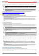
Backup Power with Smart Energy Management - System Configurations Large Residential PV Systems For residential sites with large PV systems, a StorEdge inverter and a SolarEdge single phase inverter may be installed together. The StorEdge inverter manages the battery and functions as a PV inverter, and the second inverter is used for production of the additional PV power.
Backup Power with Smart Energy Management - System Configurations Additional Capacity with Two Batteries For sites where additional battery capacity is needed (for example, to enable backed-up loads to be powered from the battery for longer periods), two batteries may be connected to a single StorEdge inverter. In this configuration, only one battery operates at any given time – i.e. the two batteries provide additional capacity only, not additional power.
Backup Power with Smart Energy Management - System Configurations 2 Set the dip switches of Battery 2 to ID 25: Move dip switch 1 to position 1 (to the left), move dip switches 2 and 3 to position 0 (to the right). Battery 1 – ID 24: Battery 2 - ID 25: 3 Configure the meter, Battery 1 and backup power as described in the Basic Configuration on page 8. 4 Configure Battery 2: 5 Select Communication RS485-1 Conf Device Type Multi-devices. A list of devices is displayed. 6 Select Battery 2.
Backup Power with Smart Energy Management - System Configurations Additional Capacity and Power For sites where additional capacity and power are needed (for example, to enable more backed-up loads to be powered simultaneously), two StorEdge inverters and two batteries may be installed 2. Each battery connects through a separate StorEdge Inverter, and each inverter manages the battery and the PV connected to it.
Backup Power with Smart Energy Management - System Configurations ► To configure the system: 1 Configure the meter, battery and backup power of inverter 1 as described in the Basic Configuration on page 8. 2 Configure the battery and backup power of inverter 2 as described in the Basic Configuration on page 8. 3 Make sure that the meter is not configured on inverter 2: Select Communication RS485-1 Conf Device Type Multi-devices. Select Meter2 Meter Type None.
Backup Power with Smart Energy Management - System Configurations ► To set up Smart Energy Management: After configuring the meter, battery and backup power, proceed with maximizing self-consumption or charge/discharge profile programming as described in the Basic Configuration on page 10. ► To verify communication: Verify communication as described in the Basic Configuration on page 11.
Backup Power Only - System Configurations Backup Power Only - System Configurations In this mode, stored energy is used for backup power only. In case of a power outage, the inverter automatically switches to backup mode, disconnecting from the grid and supplying power to backed-up loads.
Backup Power Only - System Configurations The following diagram illustrates the connection of the system components when using two batteries. In this case, an external fused combiner box is needed. For enlarged segments of this diagram refer to Appendix D – Detailed System Connection on page 45.
Backup Power Only - System Configurations Basic Configuration This configuration is based on one of each of the StorEdge components, other than the SolarEdge Electricity Meter, and is suitable for most residential systems.
Backup Power Only - System Configurations 8 If ## ≠ 01 or Prot ≠ 01, the battery and/or meter are not configured or communicating correctly. Check the configuration. Check the wiring connection. Proceed with step 10 below. 9 If ## = 01 and Prot = 01 – the battery is configured and communicating properly. Skip steps 10 to 13 below and proceed with set up backup power only as described below. 10 Select Communication RS485-1 Conf Device Type Multi-devices. A list of devices is displayed.
Backup Power Only - System Configurations S_OK: Indicates that the connection to the SolarEdge monitoring portal is successful. If S_OK is not displayed and/or errors are displayed on the LCD, refer to Errors and Troubleshooting in http://www.solaredge.com/files/pdfs/products/inverters/se-single-and-three-phase-inverter-user-manual-na.pdf. 3 For additional verification, refer to Appendix C – Verifying StorEdge Functionality on page 35.
Backup Power Only - System Configurations ► To verify communication: Verify SolarEdge inverter communication as described in the Basic Configuration on page 21. Additional Capacity with Two Batteries For sites where additional battery capacity is needed (for example, to enable backed-up loads to be powered from the batteries for longer periods), two batteries may be connected to a single StorEdge Inverter. In this configuration, only one battery operates at any given time – i.e.
Backup Power Only - System Configurations 2 Set the dip switches of Battery 2 to ID 25: Move dip switch 1 to position 1 (to the left), move dip switches 2 and 3 to position 0 (to the right). Battery 1 – ID 24: Battery 2 - ID 25: 3 Configure Battery 1 and backup power as described in the Basic Configuration on page 20. 4 Configure Battery 2: 5 Select Communication RS485-1 Conf Device Type Multi-devices. A list of devices is displayed. 6 Select Battery 2.
Backup Power Only - System Configurations Additional Capacity and Power For sites where additional capacity and power are needed (for example, to enable more backed-up loads to be powered simultaneously), two StorEdge inverters and two batteries may be installed 3. Each battery connects through a separate StorEdge Inverter, and each inverter manages the battery and the PV connected to it.
Backup Power Only - System Configurations ► To configure the inverters: Configure the battery and backup power of both inverters as described in the Basic Configuration on page 20.. ► To verify communication: Verify communication of both inverters as described in the Basic Configuration on page 21. AC Coupling using a non-SolarEdge Inverter For sites with an already installed PV system with a non-SolarEdge inverter, the StorEdge inverter can be AC-coupled to the existing inverter, i.e.
Smart Energy Management Only - System Configurations Smart Energy Management Only - System Configurations In this mode stored energy is used for Smart Energy Management applications only: Maximize self-consumption – the battery is automatically charged and discharged to meet consumption needs and reduce the amount of electricity purchased from the grid.
Smart Energy Management Only - System Configurations The following diagram illustrates the connection of the system components when using two batteries. In this case, an external fused combiner box is needed. For enlarged segments of this diagram, refer to Appendix D – Detailed System Connection on page 53.
Smart Energy Management Only - System Configurations Large Residential PV Systems For residential sites with large PV systems, a StorEdge inverter and a SolarEdge single phase inverter may be installed together. The StorEdge inverter manages the battery and functions as a PV inverter, and the second inverter is used for production of the additional PV power. An RS485 Expansion Kit (available from SolarEdge) is installed in the inverter connected to the battery.
Smart Energy Management Only - System Configurations Additional Capacity and Power For sites where additional capacity and power are needed (for example, to enable loads to be powered for longer periods and/or to enable more loads to be powered simultaneously), two StorEdge inverters and two batteries may be installed4. Each battery connects through a separate StorEdge Inverter, and each inverter manages the battery and the PV connected to it.
Smart Energy Management Only - System Configurations AC Coupling using a non-SolarEdge Inverter For sites with an already installed PV system with a non-SolarEdge inverter, the SolarEdge inverter can be AC-coupled to the existing inverter, i.e. the StorEdge inverter used to manage the battery is connected to the AC output of the existing inverter. NOTE The meter is used for Smart Energy Management and does not measure the non-SolarEdge inverter production.
Appendix A – Creating a Charge/Discharge Profile Appendix A – Creating a Charge/Discharge Profile A charge/discharge profile is created from a yearly calendar, repeated for 20 years as long as no profile changes are made. The yearly calendar is divided into segments, with one of seven charge/discharge modes assigned to each segment.
Appendix A – Creating a Charge/Discharge Profile 12 Optionally select the Exceptions tab. In this tab you can define dates that should have a specific daily profile instead of the profile defined for the relevant period. For example, if you defined a weekly profile for a period from Dec. 15 to Jan.
Appendix B - System Behavior Example Appendix B - System Behavior Example In this example the StorEdge system uses maximize self-consumption mode with zero export limit. The inverter is connected to L1 and L2 in a split phase home. It supplies loads connected to L1 and to L2 load and exports excess PV power to the grid. The produced PV power is 2kW, and there is 2kW load on L1 and a 1kW load on L2. The StorEdge system supplies 3kW to the loads – including 1kW from the battery - and exports 0kW to the grid.
Appendix C – Verifying StorEdge Functionality Appendix C – Verifying StorEdge Functionality After system installation and configuration is completed, verify that the system is properly operating: ► To verify the meter: 1 Make sure other power sources (e.g. non-SolarEdge PV inverter) are not producing power. 2 Verify the AC is ON. 3 Check the meter (installed in export or consumption position, CT arrows point to the grid): 4 Turn the inverter ON/OFF switch to OFF.
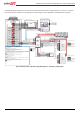
Appendix D – Detailed System Connection Appendix D – Detailed System Connection Backup Power with Smart Energy Management Basic Configuration The following diagram illustrates the connection of the system components when using the basic configuration for backup power with Smart Energy Management: one StorEdge inverter, one auto-transformer, one meter and one battery. The next diagrams are enlarged segments of this diagram.
Appendix D – Detailed System Connection Connection to utility meter Backed-up Loads Distribution Panel Main Distribution Panel Main Breaker L1 8 ft twisted pair supplied with the CT Meter is required only for Smart Energy Managment Neutral bus-bar Type B for main circuit breakers Notes 4 1/2" Conduit ARS485 B+ G L2 CT L1 CT CT L2 CT SolarEdge Meter N ØL1 ØL2 ØL3 L3 CT CB 15A CB CB 15A CB 3 Backup Panel Main Breaker 25A 25A CB CB CB CB CB CB CB CB CB CB CB CB CB 3 Inverter A
Appendix D – Detailed System Connection Figure 31: Backup Power with Smart Energy Management - Basic Configuration, Battery - StorEdge Inverter Connection 38
Appendix D – Detailed System Connection Figure 32: Backup Power with Smart Energy Management - Basic Configuration, Main Distribution Panel – Backed-up Loads Distribution Panel Connection 39
Appendix D – Detailed System Connection Table 3: Notes for Backup Power with Smart Energy Management - Basic Configuration Diagram Note Description Note 1 Recommended StorEdge inverter fuses : 12A/600VDC Quick-Acting, 10 x 38 mm Solar Midget Fuses (Example: Littelfuse P/N 0SPF012) Note 2 Auto-transformer connection: 6ft max Use 10 AWG wire for grounding Note 3 Battery connection: 35ft max Distance larger than 5ft requires installation of external DC safety switch on the battery side Control
Appendix D – Detailed System Connection Two-Battery Configuration The following diagram illustrates the connection of the system components when using two batteries. In this case, an external fused combiner box is needed. The next diagrams are enlarged segments of this diagram.
3 Inverter AC Backup [L1, L2, N], 6 AWG (4-20 AWG) 3/4" Conduit BU_L1 BU_L2 BU_N Appendix D – Detailed System Connection Backup Neutral bus-bar 3/4" Conduit PV DC- , 10 AWG (4-20 AWG), 600V insulated PV DC+, 10 AWG (4-20 AWG), 600V insulated Note 2 Fused combiner box N_BU L1_BU L2_BU L1 N L2 1" Conduit 3 RS485 [A,B,G], 24 AWG (16-24 AWG), Shielded twisted pair, 600V insulated 3 Inverter AC Grid [L1, L2, N], 6 AWG (4-20 AWG) RS485 Note 1 Fuses 12A/25A L1_Grid N_Grid L2_Grid s BAT IN 12A/600V f
Appendix D – Detailed System Connection Connection to utility meter Backed-up Loads Distribution Panel 1/2" Conduit Main Distribution Panel Main Breaker L1 8 ft twisted pair supplied with the CT Meter is required only for Smart Energy Managment Neutral bus-bar CT L1 CT CT L2 CT SolarEdge Meter L3 CT 15A CB CB 15A CB CB CB CB CB Notes 4 ARS485 B+ G L2 CB Type B for main circuit breakers 3 Backup Panel Main Breaker N ØL1 ØL2 ØL3 25A 25A CB CB Backed-up Loads Breakers To the backe
Appendix D – Detailed System Connection Table 4: Notes for Backup Power with Smart Energy Management - Two-Battery Configuration Diagram Note Description Note 1 Recommended StorEdge inverter fuses : 12A 600VDC Quick-Acting, 10 x 38 mm Solar Midget Fuses (Example: Littelfuse P/N 0SPF012) Note 2 An external fused combiner box is needed to support two batteries Note 3 Auto-transformer connection: 6ft max Use 10 AWG wire for grounding Note 4 Battery connection: 35ft max Distance larger than
Appendix D – Detailed System Connection Backup Power only Basic Configuration The following diagram illustrates the connection of the system components when using the basic configuration for backup power only: one StorEdge inverter, one auto-transformer and one battery. The next diagrams are enlarged segments of this diagram.
3/4" Conduit 3 Inverter AC Backup [L1, L2, N], 6 AWG (4-20 AWG) Appendix D – Detailed System Connection BU_L1 BU_L2 BU_N Backup Neutral bus-bar 3/4" Conduit 2 2 PV DC+, 10 AWG (4-20 AWG), 600V insulated PV DC- , 10 AWG (4-20 AWG), 600V insulated Notes 3 Notes 1 Fuses N_BU L1_BU L2_BU 1" Conduit ter AC Grid [L1, L2, N], 6 AWG (4-20 AWG) L1_Grid N_Grid L2_Grid 12A StorEdge Inverter Battery switches settings: 3/4" Conduit Battery HV DC+, 10 AWG (8-12 AWG), 600V insulated Battery HV DC- , 10 AWG (8
Appendix D – Detailed System Connection Connection to utility meter Backed-up Loads Distribution Panel Main Distribution Panel Main Breaker L1 Type B for main circuit breakers Neutral bus-bar Backup Panel Main Breaker L2 25A 25A CB CB CB Note 4 Backed-up Loads Breakers To the backed-up loads 20A 20A 20A 20A CB CB CB CB CB 3/4" Conduit 3 CB CB CB CB CB CB CB CB CB CB Inverter AC Backup [L1, L2, N], 6 AWG (4-20 AWG) BU_L1 BU_L2 BU_N Backup Neutral bus-bar 3/4" Conduit 2 2 PV DC+,
Appendix D – Detailed System Connection Table 5: Backup Power Only - Basic Configuration notes Note Description Note 1 Recommended StorEdge inverter fusesn: 12A 600VDC Quick-Acting, 10 x 38 mm Solar Midget Fuses (Example: Littelfuse P/N 0SPF012) Note 2 Auto-transformer connection: 6ft max Use 10 AWG wire for grounding Note 3 Battery connection: 35ft max Distance larger than 5ft requires installation of external DC safety switch on the battery side Control [B-,A+] must be twisted pair Note
Appendix D – Detailed System Connection Two Battery Configuration The following diagram illustrates the connection of the system components when using two batteries. In this case, an external fused combiner box is needed. The next diagrams are enlarged segments of this diagram.
25A 25A CB CB 20A 20A 20A 20A CB CB CB CB Appendix D – Detailed System Connection CB 3 CB 3/4" Conduit Inverter AC Backup [L1, L2, N], 6 AWG (4-20 AWG) BU_L1 BU_L2 BU_N Backup Neutral bus-bar 2 3/4" Conduit PV DC- , 10 AWG (4-20 AWG), 600V insulated CB PV DC+, 10 AWG (4-20 AWG), 600V insulated CB Note 2 Fused combiner box CB 3/4" Conduit CB Fuses N_BU L1_BU L2_BU CB BAT IN 12A 40A CB L1 N L2 1" Conduit 3 Inverter AC Grid [L1, L2, N], 6 AWG (4-20 AWG) L1_Grid N_Grid L2_Grid 12A/600V fuse
Appendix D – Detailed System Connection Connection to utility meter Backed-up Loads Distribution Panel Main Distribution Panel Main Breaker L1 Backup Panel Main Breaker L2 25A 25A CB CB CB CB CB CB CB CB CB CB CB CB Note 6 Type B for main circuit breakers Neutral bus-bar 3 3/4" Conduit Inverter AC Backup [L1, L2, N], 6 AWG (4-20 AWG) BU_L1 BU_L2 BU_N Backed-up Loads Breakers To the backed-up loads 20A 20A 20A 20A CB CB CB CB Backup Neutral bus-bar 2 3/4" Conduit PV DC- , 10 AWG (
Appendix D – Detailed System Connection Table 6: Backup Power Only – Two Battery Configuration notes Note Description Note 1 Recommended StorEdge inverter fuses in: 12A 600VDC Quick-Acting, 10 x 38 mm Solar Midget Fuses (Example: Littelfuse P/N 0SPF012) Note 2 External fused combiner box is needed to support two batteries Note 3 Auto-transformer connection: 6ft max Use 10 AWG wire for grounding Note 4 Battery connection: 35ft max Distance larger than 5ft requires installation of external
Appendix D – Detailed System Connection Smart Energy Management Only Basic Configuration The following diagram illustrates the connection of the system components when using the basic configuration for Smart Energy Management only: one StorEdge inverter, one meter and one battery. The next diagrams are enlarged segments of this diagram.
ØL2 ØL3 L3 CT 3 Meter AC [L1, L2, N], 12-16 AWG Appendix D – Detailed System Connection 3/4" Conduit 2 2 PV DC+, 10 AWG (4-20 AWG), 600V insulated PV DC- , 10 AWG (4-20 AWG), 600V insulated Battery switches settings: Notes 2 Fuses 12A 1" Conduit L1 N L2 s RS485 3 RS485 [A,B,G], 24 AWG (16-24 AWG), Shielded twisted pair, 600V insulated 3 Inverter AC Grid [L1, L2, N], 6 AWG (4-20 AWG) L1_Grid N_Grid L2_Grid 3/4" Conduit Battery HV DC+, 10 AWG (8-12 AWG), 600V insulated Battery HV DC- , 10 AWG
Appendix D – Detailed System Connection Connection to utility meter Main Distribution Panel Main Breaker L1 8 ft twisted pair supplied with the CT Neutral bus-bar 1" Conduit ARS485 B+ G L2 CT L1 CT CT L2 CT SolarEdge Meter N ØL1 ØL2 ØL3 L3 CT CB 15A CB CB 15A CB CB CB CB CB CB CB CB CB 3 Meter AC [L1, L2, N], 12-16 AWG 3/4" Conduit 2 2 PV DC+, 10 AWG (4-20 AWG), 600V insulated PV DC- , 10 AWG (4-20 AWG), 600V insulated Notes 2 Fuses CB CB 12A 1" Conduit CB CB CB 40A CB
Appendix D – Detailed System Connection Table 7: Basic Configuration Smart Energy Management Notes Note Description Note 1 Recommended StorEdge inverter fuses: 12A 600VDC Quick-Acting, 10 x 38 mm Solar Midget Fuses (Example: Littelfuse P/N 0SPF012) Note 2 Battery connection: 35ft max Distance larger than 5ft requires installation of external DC safety switch on the battery side Control [B-,A+] must be twisted pair 56
Appendix D – Detailed System Connection Two Battery Configuration The following diagram illustrates the connection of the system components when using two batteries. In this case, an external fused combiner box is needed. The next diagrams are enlarged segments of this diagram.
L2 CT SolarEdge Meter N ØL1 ØL2 ØL3 L3 CT 3 Appendix D – Detailed System Connection Meter AC [L1, L2, N], 12-16 AWG 3/4" Conduit PV DC- , 10 AWG (4-20 AWG), 600V insulated PV DC+, 10 AWG (4-20 AWG), 600V insulated Note 2 Fused combiner box 3/4" Conduit Fuses 12A BAT IN Batt. HV DC+, 10AWG (10-12 AWG), 600V ins. Batt. HV DC-, 10AWG (10-12 AWG), 600V ins.
Appendix D – Detailed System Connection Connection to utility meter 1/2" Conduit Main Distribution Panel Main Breaker L1 8 ft twisted pair supplied with the CT Neutral bus-bar ARS485 B+ G L2 CT L1 CT CT L2 CT SolarEdge Meter N ØL1 ØL2 ØL3 L3 CT CB 15A CB CB 15A CB CB CB 3 Meter AC [L1, L2, N], 12-16 AWG 3/4" Conduit PV DC- , 10 AWG (4-20 AWG), 600V insulated PV DC+, 10 AWG (4-20 AWG), 600V insulated CB CB CB CB CB CB Note 2 Fused combiner box 3/4" Conduit Fuses 12A CB CB BAT
Appendix D – Detailed System Connection Table 8: Smart Energy Management Only – Two Battery Configuration Notes Note Description Note 1 Recommended StorEdge inverter fuses : 12A 600VDC Quick-Acting, 10 x 38 mm Solar Midget Fuses (Example: Littelfuse P/N 0SPF012) Note 2 External fused combiner box is needed to support two batteries Note 3 Battery connection: 35ft max Distance larger than 5ft requires installation of external DC safety switch on the battery side Control [B-,A+] must be twisted
Appendix E - StorEdge Inverter without a Battery Appendix E - StorEdge Inverter without a Battery The StorEdge inverter can be used without a battery as a PV inverter with no StorEdge applications. The system can be upgraded to support StorEdge applications by adding the remaining system components.