Installation Guide Flexible Coil Current Transformer Version 1.
1 Contents Support and Contact Information 2 Flexible Coil Current Transformer Installation Overview Package Contents Installation Guidelines Installing the Flexible Coil CT in an Energy Meter with Cellular Connection Technical Specifications 4 4 6 6 Flexible Coil CT Installation Guide MAN-01-00526-1.
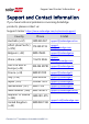
Support and Contact Information 2 Support and Contact Information If you have technical problems concerning SolarEdge products, please contact us: Support Center: https://www.solaredge.com/us/service/support Country Australia (+61) Phone 1800 465 567 E-Mail support@solaredge.net.au APAC (Asia Pacific) 073 240 3118 (+972) supportasia@solaredge.com Belgium (+32) 0800-76633 support@solaredge.be China (+86) 21 6212 5536 support_ china@solaredge.
3 Support and Contact Information Country US & Canada (+1) Phone 510 498 3200 Greece (+49) 89 454 59730 Israel (+972) 073 240 3122 Middle East & Africa (+972) 073 240 3118 South Africa (+27) 0800 982 659 Turkey (+90) 216 706 1929 Worldwide (+972) 073 240 3118 E-Mail ussupport@solaredge.com support@solaredge.com Before contact, make sure to have the following information at hand: Model and serial number of the product in question.
Flexible Coil Current Transformer Installation 4 Flexible Coil Current Transformer Installation Version History February 2019 - initial release Overview SolarEdge offers use of a Flexible Coil Current Transformer (CT; also known as Rogowski coil) as an alternative to the split core CT. The flexible coil is useful for installation in the distribution panel when there is insufficient room for installation of a split core CT.
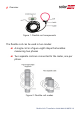
5 Overview Figure 1: Flexible coil components The flexible coil can be used in two modes: A single coil in a figure-eight shape that enables measuring two phases Two separate coils are connected to the meter, one per phase. Figure 2: Flexible coil modes Flexible Coil CT Installation Guide MAN-01-00526-1.
Flexible Coil Current Transformer Installation 6 If two coils are used, the second conditioning circuit is installed outside the meter. Package Contents Flexible coil connected to: Conditioning Circuit Twisted pair wire (black and white) This installation guide Installation Guidelines Follow these guidelines: The conductor should pass through the center of the coil, and not close to the coil’s edge, as illustrated in Figure 3.
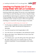
7 Installing the Flexible Coil CT in an Energy Meter Installing the Flexible Coil CT in an Energy Meter with Cellular Connection This section describes installing one or two flexible coil CTs in the Energy Meter with Cellular Connection. Two single flexible coil CTs may be used if bending one coil into a figure-8 shape is impossible for measuring two conductors.
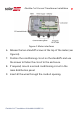
Flexible Coil Current Transformer Installation 8 Figure 4: Meter interfaces 6. Release the two standoff screws at the top of the meter (see Figure 6). 7. Position the conditioning circuit on the standoffs and use the screws to fasten the circuit to the enclosure . 8. If required, mount a second conditioning circuit in the main distribution panel. 9. Insert all the wires through the conduit opening. Flexible Coil CT Installation Guide MAN-01-00526-1.
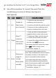
9 Installing the Flexible Coil CT in an Energy Meter 10. Use a flat screwdriver to connect the wires from the conditioning circuit(s) as follows (see Figure 5 and Figure 6): Pins Label Connect to Connection method 1. Disconnect the wires from the 1, 2 Coil Flexible coil conditioning circuit connector. (black/ white; 2. Insert the coil cable through the conduit. pre-connected) 3. Reconnect to the conditioning circuit connector according to the color code. 1.
Flexible Coil Current Transformer Installation 10 Figure 5: Conditioning circuit wiring Figure 6: Meter with a single flexibel coil 11. Open the coil by squeezing the flaps and carefully pulling Flexible Coil CT Installation Guide MAN-01-00526-1.
11 Installing the Flexible Coil CT in an Energy Meter the coil from the latch. Avoid pulling the red flexible part of the coil. Figure 7: Opening the latch 12. Bend the coil into a figure-8 shape and place around the two conductors. For best accuracy, position the latch (coil ends joint): Away from any other external line conductors Away from the conductors being measured if the coil is loose Flexible Coil CT Installation Guide MAN-01-00526-1.
Flexible Coil Current Transformer Installation 12 Figure 8: Verifying CT orientation 13. Close the CT by inserting and pressing the removable end into the latch. 14. If required, secure the CT coil to an external conductor (not the measured one) using a cable tie. To verify correct CT installation: Use this procedure to check that the figure-8 shaped flexible coil is installed in correct orientation. 1. Turn ON the AC breaker on the main distribution panel (inverter should be off).
13 Installing the Flexible Coil CT in an Energy Meter WARNING! ELECTRICAL SHOCK HAZARD. Do not touch uninsulated wires when the meter cover is removed. 2. Turn ON a home appliance (load) for power consumption (import energy). 3. Check the meter reading on the LCD screen of the meter. Import Meter Status: Power[W]: Energy[Wh]: xxxxx.x xxxxx.x 4. If the power reading is a positive value, the flexible coil is installed correctly. Otherwise, do the following: a.
Flexible Coil Current Transformer Installation 14 2. Insert the Output black and white wires of the second conditioning circuit through the meter's conduit and connect to the color coded L2CT connector. 3. Prepare a 12V DC cable sufficient for the distance between the meter and the conditioning circuit. 4.
15 Installing the Flexible Coil CT in an Energy Meter Figure 10: Power daisy chain connection 5. Place the coil around the conductors: Make sure to point the label on the cable joint (with the text: "Label toward source") towards the current source (generally the utility meter). Flexible Coil CT Installation Guide MAN-01-00526-1.
Flexible Coil Current Transformer Installation 16 Technical Specifications Installation Information Amperage Rating 250 A 8 / 2.4 ft /m 3.15 / 8.0 in / cm Coil Wire Length (from latch to conditioning circuit) Coil Length 2.4 / 8 (1) Output wires 22 AWG, twisted black/ white Frequency (nominal) Maximum voltage 50/60 Hz 600 Vac Measurement category CAT III , 600 Vac Standard compatibility UL E344623 (PICQ2); UL 61010B-1 Accuracy Basic Accuracy Conductor Position Accuracy Error ±1.
17 Technical Specifications External Conductor Accuracy Error Corner Position Accuracy Error Temperature Variation Accuracy Error ±2.5% of rated current: if an external conductor carrying the CT’s rated current is in contact with the CT, the CT output may change by up to ±2.5% of the rated current. ±1.0% maximum: if the CT is installed adjacent to a sharp bend in the conductor being measured. ±1.5% variation from: -20°C to +60°C / -4°F to +140°F Flexible Coil CT Installation Guide MAN-01-00526-1.
lf you have technical queries concerning our products, please contact our support through SolarEdge service portal: www.solaredge.