Tracer-AN Series ——MPPT Solar Charge Controller User Manual Models: Tracer1206AN/Tracer2206AN Tracer1210AN/Tracer2210AN Tracer3210AN/Tracer4210AN
Important Safety Instructions Please save this manual for future review. This manual contains safety, installation and operation for Maximum Power Point Tracking (MPPT) Tracer AN series controller ("the controller" as referred to in this manual). General Safety Information Read carefully all the instructions and warnings in the manual before installation. No user serviceable components inside the controller. DO NOT disassemble or attempt to repair the controller. Mount the controller indoors.
CONTENTS 1. General Information ........................................................................ 1 1.1 Overview.............................................. 1 1.2 Characteristics ......................................... 2 1.3 Designations of Controller Models ........................ 3 1.4 Maximum Power Point Tracking Technology ............... 3 1.5 Battery Charging Stage ................................. 4 2. Installation Instructions .............................................................
1. General Information 1.1 Overview The Tracer AN series. Based on common negative design and advanced MPPT control algorithm, with LCD displaying running status, this product is artistic, economical and practical.
The communication port adopts professional protection chip, which can provide 5VDC power supply, and has over-current and short-circuit protection. With RS-485 communication bus interface and Modbus communication protocol, it is available to meet various communication requirements in different situations.
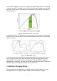
1.3 Designations of Controller Models EXAMPLE: Tracer 1 2 10 AN Common Negative System Max. PV open circuit voltage 100V System Voltage12/24VDC Charge & discharge current10A Product Series 1.4 Maximum Power Point Tracking Technology Due to the nonlinear characteristics of solar array, there is a maximum energy output point (Max Power Point) on its curve.
that the MPPT mode can improve the usage of the solar energy resource. According to our test, the MPPT controller can raise 20%-30% efficiency compared to the PWM controller. (Value may be fluctuant due to the influence of the ambient circumstance and energy loss.) Figure 1-2 Maximum Power Point Curve In actual application, as shading from cloud, tree and snow, the panel maybe appear Multi-MPP, but in actually there is only one real Maximum Power Point.
Figure 1-4 Battery changing stage Curve A) Bulk Charging In this stage, the battery voltage has not yet reached constant voltage (Equalize or Boost Voltage), the controller operates in constant current mode, delivering its maximum current to the batteries (MPPT Charging).
CAUTION: Equipment damage! Over-charging and excessive gas precipitation may damage the battery plates and activate material shedding on them. Too high an equalizing charge or for too long may cause damage. Please carefully review the specific requirements of the battery used in the system. Some types of batteries benefit from equalizing charge on a regular basis, which is able to stir electrolyte, balance battery voltage and accomplish chemical reaction.
2. Installation Instructions 2.1 General Installation Notes Please read the entire installation instructions to get familiar with the installation steps before installation. Be very careful when installing the batteries, especially flooded lead-acid battery. Please wear eye protection, and have fresh water available to wash and clean any contact with battery acid. Keep the battery away from any metal objects, which may cause short circuit of the battery.
Tracer1206/2206AN: System voltage 12V 24V System voltage 12V 24V 36 cell Voc<23V Max. Best 2 2 2 2 48 cell Voc<31V Max. Best 1 1 - 54 cell Voc<34V Max. Best 1 1 - 72 cell Voc<46V 96 cell Voc<62V Max. Best Max. Best 1 1 1 1 - - 60 cell Voc<38V Max. Best 1 1 Thin-Film Module Voc>80V - NOTE: The above parameter values are calculated under standard test conditions (STC (Standard Test Condition):Irradiance 1000W/m2,Module Temperature 25℃, Air Mass1.5.
When the controller operates under “Condition 1”or“Condition 2”, it will carry out the charging as per the actual current or power; at this time, the controller can work at the maximum power point of PV array. WARNING: When the power of PV is not greater than the rated charging power, but the maximum open-circuit voltage of PV array is more than 50(Tracer**06AN)/96V(Tracer**10AN) (at the lowest environmental temperature), the controller may be damaged.
②At minimum operating environment temperature 2.3 Wire Size The wiring and installation methods must conform to all national and local electrical code requirements. PV Wire Size Since PV array output can vary due to the PV module size, connection method or * sunlight angle, the minimum wire size can be calculated by the Isc of PV array. Please refer to the value of Isc in the PV module specification. When PV modules connect in series, the Isc is equal to a PV modules Isc.
CAUTION: The wire size is only for reference. If there is a long distance between the PV array and the controller or between the controller and the battery, larger wires can be used to reduce the voltage drop and improve performance. CAUTION: For the battery, the recommended wire will be selected according to the conditions that its terminals are not connected to any additional inverter. 2.
150 mm from the upper and lower edges of the controller to ensure natural thermal convection. Please see Figure 2-1: Mounting CAUTION: If the controller is to be installed in an enclosed box, it is important to ensure reliable heat dissipation through the box. Figure 2-2 Schematic of wiring diagram Step 2:Connect the system in the order of ❶battery ❷ load ❸PV array in accordance with Figure 2-2,”Schematic Wiring Diagram” and disconnect the system in the reverse order❸❷❶.
of PV array, battery and load can also be ungrounded, but the grounding terminal on its shell must be grounded, which may effectively shield the electromagnetic interference from the outside, and prevent some electric shock to human body due to the electrification of the shell.
3. Operation 3.1 Button Mode Note Load ON/OFF In load manual mode, it can turn the load On/Off of the load via the “ENTER” button. Clear Fault Press the “ENTER” button. Browsing Mode Press the “SELECT” button. Press the “ENTER” button. and hold on 5s to enter the setting mode Press the “SELECT” button. to set the parameters, Press the “ENTER” button. to confirm the setting parameters or exit the setting mode automatically after 10s. Setting Mode 3.
Night No charging Charging PV Voltage, Current, Power Battery capacity, In Charging Battery Battery Voltage, Current, Temperature Battery Type Load ON Load Load OFF Load Voltage, Current, Load mode 2) Fault Indication Status Icon Description Battery over discharged Battery level shows empty, battery frame blink, fault icon blink Battery over voltage Battery level shows full, battery frame blink, fault icon blink Battery over temperature Battery level shows current value, battery frame blink, fau
3) Browse interface 3.3 Setting 1) Clear the generated energy Operation: Step 1: Press the “ENTER” button and hold 5s under the PV power interface and the value is flashing. Step 2: Press the “ENTER” button to clear the generated energy.. 2) Switch the battery temperature unit Press the “ENTER” button and hold 5s under the battery temperature interface.
Item Lead-acid battery Lithium battery 1 Sealed(default) LiFePO4(4s/12V; 8s/24V) 2 Gel Li(NiCoMn)O2 (3s/12V; 6s/24V) 3 Flooded User(9~34V) 4 User(9~17V/12V; 18~34V/24V) CAUTION: When the default battery type is selected, the battery voltage control parameters will be set by default and can‟t be changed. To change these parameters, select "User" battery type. Operation: Step1: Press the “ENTER” button and hold 5s under the battery voltage interface.
CAUTION: Due to diversification of lithium battery types, its control voltage shall be confirmed with the engineer. ③ User settings (1)PC setting Connection Download software http://www.epever.com(PC Software for the Solar Charge Controller) (2)APP software setting Download software(User for lead-acid battery) http://www.epever.com (Android APP for the Solar Charge Controller) Download software(User for lithium battery) http://www.epever.
User for lithium battery. Ⅰ. Over Voltage Disconnect Voltage>Over charging protection ※ voltage(Protection Circuit Modules(PCM))+0.2V ; Ⅱ. Over Voltage Disconnect Voltage>Over Voltage Reconnect Voltage= Charging Limit Voltage ≥ Equalize Charging Voltage=Boost Charging Voltage ≥ Float Charging Voltage>Boost Reconnect Charging Voltage; Ⅲ. Low Voltage Reconnect Voltage>Low Voltage Disconnect Voltage ≥ Discharging Limit Voltage; Ⅳ.
116 117 since sunset Test mode Manual mode(Default ON) load 2n before sunrise Disabled 2n Disabled CAUTION: Please set Light ON/OFF, Test mode and Manual mode via Timer1. Timer2 will be disabled and display "2 n ". ②Load working mode settings (1)PC setting Connection Download software http://www.epever.com (PC Software for the Solar Charge Controller) (2)APP software setting Download software http://www.epever.
3.4 Accessories (optional) Remote Temperature Sensor (RTS300R47K3.81A) Acquisition of battery temperature for undertaking temperature compensation of control parameters, the standard length of the cable is 3m (length can be customized). The RTS300R47K3.81A connects to the port (4th) on the controller. NOTE: The temperature sensor short-circuited or damaged, the controller will be charging or discharging at the default temperature 25 ºC.
22
4. Protections, Troubleshooting and Maintenance 4.1 Protection PV Over Current/power PV Short Circuit PV Reverse Polarity Night Reverse Charging Battery Reverse Polarity Battery Over Voltage Battery Over Discharge Battery Overheating Lithium Battery Low Temperature Load Short Circuit Load Overload Controller ★ Overheating TVS High Voltage Transients When the charging current or power of the PV array exceeds its rated current or power, it will be charged at the rated current or power.
★When the internal temperature is 81℃, the reducing power charging mode which reduce the charging power of 5%,10%,20%,40% every increase 1 ℃is turned on. If the internal temperature is greater than 85℃, the controller will stop charging. But while the temperature decline to be below 75 ºC, the controller will resume. 4.
Check all the naked wires to make sure insulation is not damaged for serious solarization, frictional wear, dryness, insects or rats etc. Repair or replace some wires if necessary. Tighten all the terminals. Inspect for loose, broken, or burnt wire connections. Check and confirm that LED is consistent with required. Pay attention to any troubleshooting or error indication .Take corrective action if necessary. Confirm that all the system components are ground connected tightly and correctly.
5. Technical Specifications Electrical Parameters Item Tracer 1206AN Tracer 2206AN Tracer 1210AN System nominal 12/24VDC voltage Rated charge current Rated discharge current Tracer 4210AN Auto 20A 10A 20A 30A 40A 10A 20A 10A 20A 30A 40A 8~32V range ② Max. PV open 60V circuit voltage 46V Max.
Mechanical Parameters Item Dimension Mounting dimension Mounting hole size Terminal Recommende d cable Weight Tracer1206AN Tracer1210AN 172x139 x 44mm Tracer2206AN Tracer2210AN 220x154x 52mm 130x130mm 170x145mm Tracer3210AN Tracer4210AN 228x164x55mm 252x180x63mm 170x164mm 210x171mm Φ5mm 2 2 12AWG(4mm ) 6AWG(16mm ) 6AWG(16mm2) 6AWG(16mm2) 12AWG(4mm2) 10AWG(6mm2) 8AWG(10mm2) 6AWG(16mm2) 0.57kg 0.94kg 1.26kg 1.
Annex I Conversion Efficiency Curves Illumination Intensity: 1000W/m 2 Temp: 25ºC Model: Tracer1206AN 1. Solar Module MPP Voltage(17V, 34V) / Nominal System Voltage(12V) 2.
Model: Tracer1210AN 1. Solar Module MPP Voltage(17V, 34V) / Nominal System Voltage(12V) 2.
Model: Tracer2206AN 1. Solar Module MPP Voltage(17V, 34V) / Nominal System Voltage(12V) 2.
Model: Tracer2210AN 1. Solar Module MPP Voltage(17V, 34V) / Nominal System Voltage(12V) 2.
Model: Tracer3210AN 1. Solar Module MPP Voltage(17V, 34V) / Nominal System Voltage(12V) 2.
Model: Tracer4210AN 1. Solar Module MPP Voltage(17V, 34V) / Nominal System Voltage(12V) 2.
Annex II Dimensions Tracer1206/1210AN (Unit: mm) 34
Tracer2206AN/2210AN (Unit: mm) 35
Tracer3210AN (Unit: mm) 36
Tracer4210AN (Unit: mm) Any changes without prior notice! 37 Version number: 1.
BEIJING EPSOLAR TECHNOLOGY CO., LTD. Tel: +86-10-82894112 / 82894962 Fax: +86-10-82894882 E-mail:info@epsolarpv.com Website: http://www.epsolarpv.com/ http://www.epever.