SAFETY, INSTALLATION, AND OPERATIONS MANUAL FOR US INSTALLATIONS Solaria PowerXT™-R Module 3 of 11 Safety and Installation instructions © The Solaria Corporation. Contents subject to change without notice.
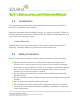
SAFETY, INSTALLATION, AND OPERATIONS MANUAL 1.0 Introduction This document provides safety and installation information for the Solaria PowerXTTM residential solar modules. Read this document before installing, wiring, or using this product. Failure to comply with these instructions will invalidate the Solaria Limited Warranty and may cause loss, damage or injury. Limited Warranty Module limited warranty is described in The Solaria Corporation PowerXTTM Warranty. Warranty details may be found at www.
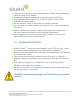
There are no user serviceable parts within the module. Do not attempt to repair any part of the module. Installation should be performed by authorized personnel only. Use insulated tools to reduce risk of electric shock. Do not touch terminals with bare hands. Do not stand on, drop, or allow objects to fall on modules. Do not install or handle modules when they are wet or during periods of high wind.
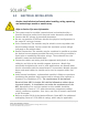
3.0 ELECTRICAL INSTALLATION Caution: Avoid all electrical hazards when installing, wiring, operating, and maintaining a module or module array. Refer to Section 2 for more information. The system must be installed, commissioned and maintained by a licensed electrician unless local electrical codes determine otherwise. Contact with DC voltage is potentially hazardous. Do not use modules of different electrical or physical configurations in the same DC string or inverter.
All Solaria modules are equipped with factory locking connecting cables. Modules have been designed to be easily connected. The locking connectors are not to be disconnected under load. The proper procedure to disconnect the module locking connectors is as follows: Turn off the inverter(s), shut off the module DC disconnect(s) and then disconnect the locking connectors using an approved tool set.
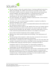
3.1 Grounding (Grid-tied applications) Before installing your solar system, contact local authorities to determine the necessary system hardware grounding requirements. Module frames should be electrically connected to an earth ground for safety and protection from lightning in accordance to the National Electric Code (NEC). Refer to NEC article 250 on grounding PV arrays for specific requirements.
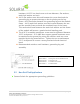
hardware (#10-32 hex head screw at 4 mm diameter, flat washers, tooth lock washer and nut). A #10 flat washer must be used between the screw head and the grounding lug to prevent damage to the tin plating on the lug. Insert a #10 flat washer between the grounding lug and the module frame. A #10 tooth lock washer must be inserted between the nut and the module frame to break the anodized layer of the frame.
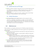
4.0 Module Mounting The Solaria Corporation PowerXTTM Warranty is contingent upon modules being mounted in accordance to the requirements described in this section. 4.1 Site Considerations Solaria modules should be mounted in locations that meet the following requirements. Module should not be mounted in locations where it will be in direct contact with salt water. When choosing a site, avoid obstructions that could cast shadows on the modules. 4.
Do not remove or alter the module frame. Creating additional mounting holes may damage the module and reduce the strength of the frame. The Solaria modules must be mounted using industry standard ground mount hardware roof mount hardware, or single and dual axis PV trackers. If other mounting means are employed, then product certification or fire class ratings may be affected. For roof mounting, the modules should be mounted over a fire-resistant covering rated for the application.
4.3 Module Direction and Tilt Angle Modules produce maximum energy when they are pointed directly to the Sun. Modules get maximum sunlight throughout the year if they face South in Northern Hemisphere and they face North in Southern Hemisphere. When mounted on a single axis tracker, modules may be tilted or kept horizontal. Tilting will produce more annual energy. 4.
6.0 Disclaimer of Liability Since the use of this Safety, Installation and Operation Manual and the conditions or methods of installation, operation, use and maintenance of the module are beyond The Solaria Corporation control, The Solaria Corporation does not assume responsibility and expressly disclaims liability for loss, damage, injury or expense arising out of or in any connection with such installation, operation, use or maintenance of the module.
7.0 Electrical Specifications ELECTRICAL PARAMETERS Peak Power, Pmax (Watts) 330 Open Circuit Voltage, Voc (V) 44.5 Short Circuit Current, Isc (A) 9.49 Voltage at Pmax (V) 36.6 Current at Pmax (A) 9.2 Max Series Fuse Rating (A) 15 UL Max System Voltage (V) 1000 TEMPERATURE SPECIFICATIONS Coefficient of Power Coefficient of Voltage Coefficient of Current -0.40 %/°C -0.32 %/°C +0.
8.0 Mechanical Dimensions Module Weight: 20.1 kg (44.31 lbs.) Nominal dimensions in millimeters and [inches] – Not Drawn to Scale Safety and Installation instructions © The Solaria Corporation. Contents subject to change without notice.
Solaria USA 6200 Paseo Padre Pkwy Fremont, CA 94555 United States of America T: +1-510-270-2500 www.solaria.com Safety and Installation instructions © The Solaria Corporation. Contents subject to change without notice.