Sumo Class Inlet Filters F Series 16” – 24” Flange www.solbergmfg.com Note: Please read the maintenance instructions given by the OEM for the machinery first. The OEM's manual should be adhered to in order to protect the equipment. Solberg Manufacturing, Inc has made every effort to make sure that these instructions are accurate but is not responsible for any typos, slight variations or for human errors that may occur. Solberg Manufacturing, Inc., 1151 Ardmore Itasca, IL 60143 USA Ph: 630.773.
Maintenance Manual Sumo Class Inlet Filters F Series 16” – 24” Flange CONTENTS Section A Introduction ....................................................................................... pg. 3 Section B General Information 1. Identification of Solberg Filters .......................................... pg. 3 2. Filtration Rules of Thumb .................................................. pg. 4 3. Element Specifications. ..................................................... pg. 6 4. Element Cleaning .....
Section A INTRODUCTION The purpose of this manual is instruction on the proper assembly and care of Solberg inlet air filters. *WARNING* This manual must be read and thoroughly understood before using and caring for this air filter. Failure to comply could result in explosion, product/system contamination or personal injury. This manual should be used as a supplement to the user’s understanding of the proper care needed to maintain a safe and dependable air filter.
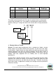
No. Filter Model Number Replacement Element Initial Delta P Readings 1 2 3 4 5 Table 1 The model number designates the filter type, the original element configuration and housing connection size. For example, the following part number identifies the filter as being a ‘F’ design filter with a 491 element and 18” flange connection size: F - 491-1800F Filter Type: 2G, QB, FS, F and FT Element Type: Size, Material, Prefilter, Micron Rating Connection Size and Type 2.
Rule of Thumb #1: Always begin with the filter cartridge requirements when sizing a filter. Once the appropriate element has been selected then move on to the housing requirements. Rule of Thumb #2: Always ask or specify a filter based on a micron rating with filtration efficiencies. As an example, stating a requirement for a 1-micron filter is misleading because no efficiency rating has been specified. A 1-micron filter at 95% efficiency may be less efficient than a 5-micron filter at 99% efficiency.
Rule of Thumb #4: Pressure drop is also caused by the dirt holding capacity of the element. As the element fills up with dirt, the pressure drop increases. It is important to document the pressure drop across a given filter when it is new and then clean or replace it when the pressure drop increases by 10” to 15” / 250280mm H2O over the original reading. Rule of Thumb #5: The inlet connection greatly influences the overall pressure drop of the filter system.
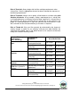
4. Element Cleaning - Inlet Filtration Solberg elements should be cleaned or replaced, once the pressure drop reaches 15 to 20-inches water column (380 - 500mm WC) above the initial pressure drop of the installation. The decision to clean the element rather than replace it is left to the discretion of the operator. Any damage which results from by-pass or additional pressure drop created by element cleaning is the sole responsibility of the operator.
C. Polyurethane Prefilter: The prefilter may be washed as a sponge or replaced to give the element a longer service life. D. Epoxy Coated Wire Mesh and Stainless Steel Wire Mesh Elements: Cleaning instructions similar to polyester, except mild solvents may be used. E. Activated Carbon Element: Not cleanable F. Polypropylene Element: Cleaning instructions similar to polyester G.
A. Maximum operating temperature for most Solberg inlet air filter products is 220°F / 105°C. Temperatures in excess of this could cause damage to elements, media and elastomers. High temperature products are available. B. Direction of flow is typically from the outside of the element to the inside of the element. Most products have arrows indicating direction of flow on the inlet and outlet ports. C.
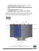
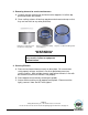
3. Removing element for service/maintenance. A. Carefully remove retaining nut and washer over top plate. Lift off the top plate and remove the element. B. Clean sealing surfaces of housing, top plate and element end caps so that they are free of dirt or any other particulate. Figure C.3.1: Removal of hex nut, washer, and top plate. Figure C.3.2: Element sitting in housing base. Figure C.3.3: Element with gaskets.
Figure C.4.1: Element properly secured in housing base. *WARNING* Defective installation may cause system or pump contamination. Use only genuine Solberg replacement parts. 5. Securing canister top to canister base. A. Make sure all surfaces are free from dust and other particulate. B. Replace cover. Feed threaded bolt into corresponding bolt holes and secure with washer and hex nut. Note: Do NOT over tighten! Figure C.5.1: Housing top and hex nuts in secured position. Page 11 Solberg Manufacturing, Inc.
6. Equipment Startup. A. Be sure to read the instructions on installation or element replacement as listed above before starting equipment. *WARNING* If at any time the operator is unable to verify the integrity of the element or any housing feature, the factory or a regional representative should be contacted prior to start-up. B. Please check the listed steps prior to startup. 1. Check element to make sure it is seated properly on element base or sealing surface.
Section D MAINTENANCE RECOMMENDATIONS 1. Pressure drop readings are recommended to have an effective air filter. Always document initial pressure drop during start-up when element is clean. Replacement cartridge is needed when system experiences 10” to 15” / 250380mm H2O above drop above the initial reading. Refer to page 4 for initial values. 2. Always check inlets/outlets, element base and its components when replacing element to insure cleanliness. Wipe clean if necessary. 3.