
Specification Sheet
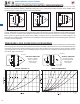
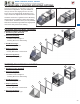
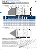
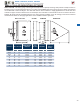
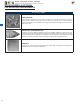
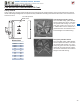
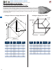
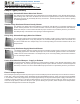
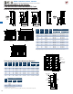
Table Of Contents

322
Fan
Size
A
(S.Q.)
O.D.
Wall Housing
Minimum
Wall Opening
Filter Box
B Length
C D
# of
Filters
Filter
Actual Dimensions
GED & DFE Only DDE/DDS
Exhaust Supply Exhaust Supply Square
14/16 21 26 26 N/A N/A 21 1/2 21 39 2 19 5/8 x 19 5/8 x 1 7/8
18/20 25 26 26 N/A N/A 25 1/2 25 44 1/8 3 19 5/8 x 24 5/8 x 1 7/8
24 31 44 44 44 44 31 1/2 31 41 1/8 4 19 5/8 x 24 5/8 x 1 7/8
30 37 44 44 44 44 37 1/2 37 44 1/8 8 15 5/8 x 24 5/8 x 1 7/8
36 43 N/A N/A 44 44 43 1/2 43 44 1/8 8 19 5/8 x 24 5/8 x 1 7/8
42 49 N/A N/A 44 44 49 1/2 49 44 1/8 10 19 5/8 x 24 5/8 x 1 7/8
48 55 N/A N/A 44 44 55 1/2 55 40 1/2 12 19 5/8 x 24 5/8 x 1 7/8
54 61 N/A N/A 44 44 61 1/2 61 44 1/8 15 19 5/8 x 24 5/8 x 1 7/8
60 67 N/A N/A 44 44 67 1/2 67 44 1/8 15 19 5/8 x 24 5/8 x 1 7/8
FILTERED WALL HOUSING MOUNTING OPTIONS Cont.
Filtered Wall Housing Dimensions
Filtered Supply
Filtered Exhaust
Use the estimated pressure drop graphs to help select
the proper exhaust or supply fan that will deliver the
desired airow. Enter the graph from the bottom at
the specied CFM and move vertically upward to the
fan curve for the desired size, then horizontally to
the left and read the estimated static pressure drop
resulting from these typical accessory packages. Add
the accessory pressure loss to the system (or building)
design static pressure loss to obtain the total static
pressure loss to be used for the proper fan selection.
PRESSURE LOSS GUIDE FOR FILTER BOX
Optional Rainhood
(90 deg. supply)
Optional
Damper
A
B
C
D
Mounting
Flanges
Wall
Mounting Flanges
Filter
Box
Wall
Housing
Lifting
Lugs
Optional Rainhood
(45 deg. exhaust)
A
B
C
D
Optional
Damper
Mounting
Flanges
Wall
Mounting Flanges
Filter
Box
Wall
Housing
Lifting
Lugs
MODELS GED/GSD, DFE/DFS, DDE/DDS
DIRECT DRIVE SIDEWALL PROPELLER FANS