
Specification Sheet
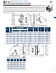
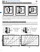


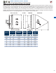
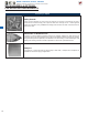
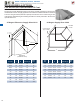
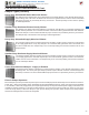
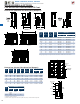
Table Of Contents

320
SIZES 30 THROUGH 60
Use the estimated pressure drop graphs to help select the proper exhaust or supply fan that will deliver the desired airow.
Enter the graph from the bottom at the specied CFM and move vertically upward to the fan curve for the desired size, then
horizontally to the left and read the estimated static pressure drop resulting from these typical accessory packages. Add the
accessory pressure loss to the system (or building) design static pressure loss to obtain the total static pressure loss to be
used for the proper fan selection.
EXHAUST AIRFLOW
with WALL HOUSING,
GRAVITY DAMPER,
RAINHOOD AND
FLAT GUARD
SUPPLY AIRFLOW
with WALL HOUSING,
MOTORIZED DAMPER,
RAINHOOD AND
FLAT GUARD
SIZES 10 THROUGH 24
45 Degree
90 Degree
PRESSURE LOSS GUIDE FOR ACCESSORIES
Wall housing ush with inside wall
and projecting outside the building
Wall housing centered within wall
Wall housing ush with outside wall
and projecting inside the building
The most common mounting arrangement (below left) leaves a clean building exterior and allows access to the fan, motor
and drives from inside the building. Additional bracing angle, rod or cable (eld provided) should be used in addition to the
mounting angles to support the fan and wall housing assembly.
NOTE: Supply applications have the fan venturi spun on the opposite side of the fans shown above. The fans shown are
exhaust. Rainhoods are required on supply applications and recommended on exhaust applications where additional weather
protection is desired. Exhaust and/or supply fans installed as shown should be serviced from the interior of the building.
Where service is required from the exterior of the building, consult the factory or representative for recommendations. All
bracing shown is eld provided. Field ashing and caulking of wall housing seams and unused mounting holes, will ensure
a weather resistant installation.
WALL HOUSING STANDARD MOUNTING ARRANGEMENTS
MODELS GED/GSD, DFE/DFS, DDE/DDS
DIRECT DRIVE SIDEWALL PROPELLER FANS