PACKAGED TERMINAL AIR CONDITIONER Installation and Operating Instructions Model No.
CONTENTS IMPORTANT NOTE TO THE SERVICER UNIT FEATURES… ………………………………………… 2 Read this manual and familiarize yourself with the specific items which must be adhered to before attempting to service this unit. The precautions listed in this Installation Manual are intended as supplemental to existing practices. However, if there is a direct conflict between existing practices and the content of this manual, the precautions listed here take precedence.
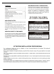
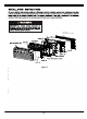
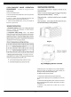
control panel Figure 1
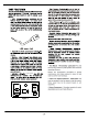
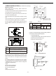
• Fan Motors Permanently Lubricated-All units have two fan motors for quiet operation and maximum operating efficiency. UNIT ACCESSORIES This unit is designed for through-the-wall installation in new or existing buildings. To complete the installation of this PTAC, an insulated wall sleeve and an outdoor grille (either the stamped aluminum grille, or the architectural grille ) are required.(not included in this package).
Wall Sleeve (not included in the package) Figure 2 Outdoor Grille (not included in the package)
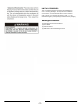
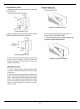
SLEEVE INSTALLATION (not included in the package) MAIN STUD JACK STUDS HEADER-4"×4"OR 2-2"×4"ON EDGE Wall sleeve location When making the wall opening, please observe the following requirement: 16-1/4"MIN A) The air inlet and outlet should be unblocked and the air can be delivered to every corner of the room ADJUSTABLE FRAMING TO SECURE THIS DIMENSION 42-1/4"MIN B) Install the unit in places that are away from heat source or sources of flammable gases.
OUTDOOR GRILLE(OPTIONAL ACCESSORY) 4. Secure the chassis to the wall sleeve using three screws on each side of the chassis to ensure a proper seal between the chassis and the wall sleeve. The screws are supplied in a plastic bag. An outside grille must be installed to direct air flow for proper unit operation and also protect the outdoor coil. The grille must be installed before installing the chassis.
* Heat function & wire do not applied this model.
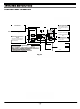
CONTROL PANEL OPERATION Fan Speed Button Press this button to select the fan speed on high, low, or auto. Mode Buttons Press these buttons to select Cool Mode or Fan mode. FAN SPEED *Heat mode does not apply to this model Fan speed indicator lamps. s indicator Operation status lamp. Operation Mode Indicator Lamps When the unit in Cool mode or Fan mode, the mode indicator lamps will light up. ON/OFF Button Press this button to turn the unit ON or OFF.
: unit control panel has control of unit. COOL/FAN/HEAT MODE OPERATION PROCEDURE * Hear Mode does not apply to this model : wall thermostat has control of unit. Control panel: Press the ON/OFF button. 11 VENTILATION CONTROL Press the HEAT/COOL/FAN button, select the operation mode: heat/cool/fan. 12. The ventilation control lever is located at left side of unit, behind front panel. Press + or - button, to set your desired temperature. The setting temperature range is 60-90°F(16-32°C).
Discharge Air Flow WARNING 3. Remove the seven (7) screws which secure the discharge air grille to the cabinet front. HIGH VOLTAGE DISCONNECT ALL POWER BEFORE SERVICING OR INSTALLING THIS UNIT. MULTIPLE POWER SOURCES BE PRESENT, FAILURE TO DO SO MAY CAUSE PROPERTY DAMAGE, PERSONAL INJURY OR DEATH. Location of 7 Screws Discharge Air Flow Grille Removal 4. Rotate the grille 180° clockwise 5. Reinstall the screws securing the discharge air grille to the cabinet front.
2. Pull the filter straight up and remove. Routine scheduled Maintenance 3. Clean filter with vacuum or with running water. To achieve continuing top performance and high efficiency, establish a “once a year" cleaning/inspection schedule for the unit. Take the unit out of the sleeve and thoroughly clean and rinse. Be sure to include in the yearly cleaning the evaporator coil, and condenser coil, basepan, and drain passages. Reverse this procedure to reinstall the filter.
4. Tilt the non-compressor side of the unit up no higher than 45 degrees and allow water to drain out the other side of the unit. Air sounds The fan cycle switch sets the operational mode of the fan. In the ON position the fan will run continuously whenever power is applied in this mode. In the AUTO position, the fan will cycle on and off with the compressor or electric heater. 5. Remove excess water left in the base pan by wiping the base pan with a dry cloth. 6.
WARRANTY Soleus N.A warrants the accompanying Soleus Air PTAC to be free of defects in material and workmanship for the applications specified in its operation instruction for the period of labor and parts specified below. 5 YEARS FOR COMPRESSOR 1 YEAR FOR OTHER COMPONENTS This warranty shall not apply to broken or marred cabinets, accessories, knobs, filters or routine maintenance.