Models SG-WAC-15ESE-C SG-WAC-18ESE-C Electronic Window A/C Operating Instructions V.
Thank you for choosing a Soleus Air powered by Gree Air Conditioner. This owner’s manual will provide you with valuable information necessary for the proper care and maintenance of your new product. Please take a few moments to thoroughly read the instructions and familiarize yourself with all the operational aspects of your new air conditioner. For your own records, please attach a copy of your sales receipt to this manual.
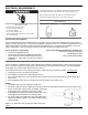
ELECTRICAL REQUIREMENTS The electrical ratings for your air conditioner are listed on the model and serial number label located on the front left side of the unit (when facing the front). Specific electrical requirements are listed in the chart below. Follow the requirements below for the type of plug on the power supply cord. Power Supply Cord Electrical Shock Hazard Plug into a grounded 3 prong outlet. Do not remove the ground prong. Do not use an adapter Do not use an extension cord.
PARTS LIST WINDOW SASH SEAL SAFETY LOCK AND 3/4" ROUND-HEAD SCREW TOP ANGLE FOAM GASKET FRAME ASSEMBLY (LEFT) SIDE RETAINER SEAL-BOTTOM RAIL TO UNIT 1/2" LONG SCREWS AND LOCKNUTS LOCKNUT 3/4" LONG FLAT HEAD BOLT TOOLS NEEDED FRAME ASSEMBLY (RIGHT) Large Flathead Screwdriver Tape Measurer Adjustable Wrench or Pliers Pencil Level Socket Wrenches Phillips Head Screwdriver WINDOW SUPPORT BRACKET SILLANGLE BRACKET Non-Hardware Packing List • • • • • • • • • Window Air Conditioner AAA Batteries (2) T
SPECIFICATIONS • Noise level is measured at a distance of 3.28 ft away from the front of the unit in cooling mode. • Power consumption is measured when the fan runs at the highest speed setting. • These specifications are for reference only. For actual data, please refer to the rating label on the back of the unit. Model SG-WAC-15ESE-C Power Supply (Ph/V/Hz) Rated Cooling Capacity (BTU/h) Cooling Power Input (Watts) Rated Current Cooling (Amperage) EER/C.O.
INSTALLATION & ASSEMBLY INSTRUCTIONS Window Preparation Please read all instructions prior to installing your air conditioner. Two people are recommended to install this product. If a new electrical outlet is required, have the outlet installed by a qualified electrician before installing the unit. Before installing the unit, check the dimensions of your window to make sure the air conditioner will fit. This unit is made to fit inside a standard double-hung window.
INSTALLATION & ASSEMBLY INSTRUCTIONS - WINDOW MOUNTING REMOVE CHASSIS 1. Pull down the front panel and remove the filter (FIG. 1 below) 2. Lift the front panel upwards to remove and place to the side. FIG. 1 FIG. 1 FIG. 2 3. Locate the four faceplate screws and remove. These screws will need to be re-installed prior to mounting the air conditioner (FIG. 2 above) 4. After removing the screws, gently pull away the faceplate from the air conditioner cabinet (FIG. 3 & 4). FIG. 3 FIG. 4 5.
INSTALLATION & ASSEMBLY INSTRUCTIONS - WINDOW MOUNTING REMOVE CHASSIS 1. Pull down the front panel and remove the filter (FIG. 1 below) 2. Lift the front panel upwards to remove and place to the side. FIG. 2 FIG. 1 3. Locate the four faceplate screws and remove. These screws will need to be re-installed prior to mounting the air conditioner (FIG. 2 above) 4. After removing the screws, gently pull away the faceplate from the air conditioner cabinet (FIG. 3 & 4). FIG. 3 FIG. 4 5.
INSTALLATION & ASSEMBLY INSTRUCTIONS - WINDOW MOUNTING REMOVE CHASSIS 6. Remove the screws from the right side of the cabinet (FIG 7). FIG. 7 7. Hold the cabinet while pulling on the base handle to carefully remove the unit. Do not pull or lift near the top of the unit (FIG 8). FIG.
ASSEMBLY & INSTALLATION (CONT.) Top Angle Rail and Side Bracket Installation 1. 2. 3. 4. FIG. 9 Place the air conditioner on a hard flat surface. Locate the foam gasket and top angle rail Attach the foam gasket to the top angle rail Install top angle side to cabinet as shown in FIG 7 TOP VIEW Foam Gasket and Top Angle Rail FIG. 7 Placing the Cabinet Inside the Window 1. Open the window and place the cabinet in the middle of the window sill. 2.
Install Support Brackets 1. Hold each support bracket flush against the outside of the window sill. Tighten each bracket to the bottom of the cabinet as shown below. Mark the brackets at top lever of the window sill and then remove. Mark Left 1/2” Long Screws and Locknuts Locknut Sill Angle Bracket Flat Head Bolt Right Extend the Accordion Panels 1. Carefully raise the window to expose the accordion panel and panel frame. Loosen the locking screws so the accordion panels slide easily. 2.
ASSEMBLY & INSTALLATION (CONT.) Installing the Chassis into the Cabinet 1. Team lift (two people) the air conditioner chassis and carefully slide it into the cabinet. Let the front of the air conditioner hang out approximately 6”. 2. CAUTION: DO NOT PUSH ON THE CONTROLS OR FINNED COILS. 3. Be sure the chassis is firmly seated in the back of the cabinet. 4. Insert all screws removed during window installation and reattach the front face plate, front panel, and the air filter.
ASSEMBLY & INSTALLATION - THRU-THE-WALL (CONT.) Carefully measure and cut an opening with the following dimensions depending on your model (FIG. 1 & 2). WIDTH “X” = inside model plus twice the thickness of the framing material used. HEIGHT “Y” = inside model height plus twice the thickness of framing material used.
ASSEMBLY & INSTALLATION - THRU-THE-WALL (CONT.) Refer to the SUPPORT BRACKET ASSEMBLY in the WINDOW MOUNTING section to assemble the support brackets. A wooden strip nailed to the outside wall should be used in conjunction with the angled sill support brackets. FIG. 3 Support Bracket Wooden Strip 5. Screw or nail the cabinet to the wooden frame using shims if the frame is oversized, to eliminate possible noise. Remember to maintain proper slope for water elimination. MASONRY CONSTRUCTION 1.
USING YOUR AIR CONDITIONER Electronic Control Panel & Remote Control NOTE: This display always shows the room temperature in Fan Mode except when setting the Set temperature or the Timer. When the light is on the unit is in temperature or timer set mode. 3. Temperature Set: Use these buttons on the control panel and remote to increase or decrease the Set Temperature (the desired room temperature) in cooling,energy saver and dry mode. The SET light will light up when setting the temperature 4.
OPERATING YOUR AIR CONDITIONER REMOTE CONTROL 1. ON/OFF - Press the ON/OFF button to turn the A/C on or off. When the unit is turned off, the Timer and sleep functions will be cancelled. The set temperature will be saved. 2. MODE - Press the MODE button to change the operating mode. You can choose AUTO, COOL, SAVE (energy saver), FAN only, or Dry (Dehumidifier). The temperature will not be displayed when AUTO mode is selected. 3. “—”- Press the “-” button to decrease the temperature when the unit is on.
OPERATING YOUR AIR CONDITIONER REMOTE CONTROL 9. LOCK/UNLOCK- Press the “+” and “—” buttons simultaneously to lock and unlock the remote control. When the remote is locked, none of the functions or setting can be changed using the remote. 10. F° or C° - To switch between the F° or C° settings, press the MODE and “—” buttons at the same time. 11. DISPLAY LIGHTS- Hold the “+” and FAN buttons to turn the lights on the display ON or OFF. This can be done when the unit is on or off. 12.
USING YOUR AIR CONDITIONER (Cont.) • Freezing Conditions: This is a cooling only air • conditioner. It is not designed for freezing outdoor conditions. It must not be used in freezing outdoor conditions. • Remote Control: To ensure proper operation when using the remote control, aim the remote directly at the signal receiver on the air conditioner. • The remote control has a signal range up to 20 feet. NOTE: Auto Fan Speed cannot be used in Fan Only mode.
CARE AND CLEANING Clean your air conditioner to keep it looking new and to minimize dust build up. Cabinet Cleaning To clean the air conditioner cabinet: • Air Filter Cleaning The air filter should be checked at least once every month to see if it needs cleaning. Trapped particles and dust can build up in the filter and may decrease airflow as well as cause the cooling coils to accumulate frost. To clean the air • filter: 1.
TROUBLESHOOTING PROBLEM POSSIBLE CAUSES SOLUTIONS The Air Conditioner will not start The air conditioner is unplugged • Make sure the air conditioner is plug is pushed completely into the outlet The fuse is blown/circuit breaker is tripped. • Check the house fuse/circuit breaker box and replace the fuse or reset the breaker. Power Failure • The unit will automatically re-start when power is restored. There is a protective time delay (approx.
TROUBLESHOOTING (CONT.) PROBLEM POSSIBLE CAUSES SOLUTIONS Water is dripping outside Hot and Humid weather. • This is normal Water is dripping inside the room The air conditioner is not correctly tilted outside. • For proper water drainage, make sure the air conditioner is slightly tilted downward from the front of the unit to the rear. Water collects in the base pan Moisture removed from the air is draining into the base pan.
Warranty Soleus International Inc. warrants the accompanying Soleus Air Air Conditioner to be free of defects in material and workmanship for the applications specified in its operation instruction for the period of parts specified below. 5 YEARS FOR COMPRESSOR 1 YEAR FOR OTHER COMPONENTS This warranty shall not apply to broken or marred cabinets, accessories, knobs, filters or routine maintenance.