Multichannel Compressor Owner’s Manual
Solid State Logic SUPER ANALOGUE MULTICHANNEL COMPRESSOR Super-Analogue™ Outboard Owner’s Manual 82S6XL010D
XLogic Multichannel Compressor Owner’s Manual Solid State Logic Begbroke, Oxford, England, OX5 1RU • +44 (0)1865 842300 320 West 46th Street, 2nd Floor, New York, NY 10036, USA • +1 (1) 212 315 1111 Suite 401, 5757 Wilshire Blvd, Los Angeles, CA 90036, USA • +1 (1) 323 549 9090 3-55-14 Sendagaya, Shibuya-Ku, Tokyo 151-0051, Japan • +81 (0)3 5474 1144 7 bis, rue de la Victoire, le Blanc Mesnil, Paris 93150, France • +33 (0)1 48 67 84 85 Via Timavo 34, 20124 Milano, Italy • +39 (0)39 2328 094 Visit SSL at U
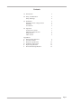
Contents 1.0 Introduction 3 2.0 Safety Considerations Safety Warnings 4 4 3.0 Installation Setting the mains voltage selector Mounting Connections 6 6 6 6 4.
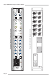
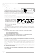
Solid State Logic 4 Page 2 12 LFE/ ST B A dB COMPRESSION 8 METER 16 IN IN 100V 120V 220V 240V +20 -20 +20 THRESHOLD -20 THRESHOLD .1 .1 .3 .3 30 1.5 2 RATIO 3 4 20 30 1.5 2 RATIO 3 4 5 5 10 10 1 1 .2 RELEASE - S .4 .8 1.6 RELEASE - S .4 .8 1.6 .
Introduction 1.0 Introduction The XLogic Multichannel Compressor is a 2U rack-mounting six-channel compressor. It utilises classic SSL Centre Section compressor design elements within a SuperAnalogue design topology. This brings the dual benefits of spectacular surround audio performance with a universally acclaimed compressor characteristic. The unit contains two separate compressors.
XLogic Multichannel Compressor Owner’s Manual 2.0 Safety considerations This section contains definitions and warnings, and practical information to ensure a safe working environment. Please take time to read this section before undertaking any installation work. 2.1 Definitions ‘Maintenance’ All maintenance must be carried out by fully trained personnel. Note: it is advisable to observe suitable ESD precautions when maintenance to any part is undertaken.
Safety Considerations Mains Supply and Phases Solid State Logic equipment is designed for connection to single phase supplies with the Neutral conductor at earth potential – category TN – and is fitted with a protective fuse in the Live conductor only. It is not designed for use with Phase (Live) and Neutral connections reversed or where the Neutral conductor is not at earth potential (TT or IT supplies).
XLogic Multichannel Compressor Owner’s Manual 3.0 Installation 3.1 Voltage Selection Before connecting the mains supply ensure that the voltage range selector next to the IEC socket on the rear of the unit is correctly set. The input setting must be confirmed before applying power. The input module can be configured to be one of 4 voltage settings. The setting is indicated by a plastic pin protruding through the appropriate hole in the fuse panel - the example shown here is set for 240V operation.
Installation and Operation 4.0 Operation The XLogic Multichannel Compressor unit is a 2U rack-mounting six-channel compressor designed to provide extremely flexible control over a 5.1 channel mix, or to be used as two separate compressors when working on stereo material. The compressor design is very similar to that found in the XL 9000 console centre section, but with additional controls to provide the flexibility that modern 5.1 productions require.
XLogic Multichannel Compressor Owner’s Manual The ISO switches isolate their respective channels from the compressor. When pressed that channel will not contribute to the side chain and will not be affected by the compressor. It is still controlled by the Master Fader and AutoFade controls. Another example may help: your mix has low level stereo reverb placed in the surround channels. You don’t want this to be affected by the front channels so you press the Surround ISO switch in.
Appendix Appendix A – Internal links and fuses Fuses (Mains Inlet) The mains inlet contains a single 1 amp 1.25" time delay fuse (SSL Part No. 35FJJ310). To change it disconnect the mains inlet, then using a small screwdriver prise open the mains selector cover. This contains the fuse. Test and replace with the same type and value if necessary. Internal Fuses The internal power rails are also individually fused. These fuses should only be changed by suitably experienced staff.
XLogic Multichannel Compressor Owner’s Manual Appendix C – Performance Specification Conditions Source impedance 50Ω unless otherwise stated. All measurements are RMS and are made using a 22Hz to 22kHz filter unless otherwise stated. Noise Input terminated with 50Ω. Compressor switched in and set for 0dB gain. Noise < 99dBu Headroom Headroom is defined at the output level at which THD exceeds 1%.
Appendix Appendix D - Calibration Information The XLogic Multi Channel compressor is factory calibrated and should only need calibration if a potentiometer or other component has been replaced or if it is suspected that there is a problem with calibration. In all of the following instructions it is assumed that the lid has been removed and that power has been applied.
XLogic Multichannel Compressor Owner’s Manual Distortion Null Equipment Required: Calibrated audio oscillator, audio distortion analyser and oscilloscope Test Signal: 1kHz sinewave at +24dBu Input and Output: Oscillator to the Input of the channel being tested, Output to the distortion analyser. Use the oscilloscope to monitor the measured signal. Adjustment: 1. Connect the +ve input of the analyser to the test point as shown below and connect the –ve input of the analyser to a 0VA test point.
Appendix Appendix E – Physical specification * Depth: 325mm/12.8 inches not including heatsink 365mm/14.3 inches including heatsink 400mm/15.75 inches including connectors Height: 89mm/3.5 inches (2 RU) Width: 480mm/19 inches Weight: 5kg/11 pounds Power: 55 Watts/67 VA Boxed size: 520mm x 520mm x 182mm (20.5" x 20.5" x 7.2") Boxed weight: 7.3kg (16 pounds) * All weights and dimensions are approximate Appendix F – Environmental Specification Temperature Operating: Non-operating: Max.
XLogic Multichannel Compressor Owner’s Manual Notes Page 14