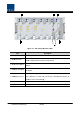
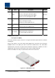
Fig gure 4.7 – BIU B front pan nel Outer Lo ook Item 1. MDB BU LED 2. RF Monitor M Port 3. Alarrm LED & Re eset 4.
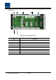
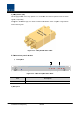
) Re ear panel Figure 4.8 – Rear panell Outer Look k Item Descrip ption 1. External ALM M Port Input/output terminal for dry contact 2. GSM Modem m Port GSM Modem m terminal fo or upper netw work (Optiona al) 3. V/UHF V I/O Port P RF signal intterface termiinal of VHF& &UHF 4. ODU I/O Porrt RF signal intterface termiinal for ODU 5. ODU signal Port Power and signal s interface terminal for f ODU 6. BTS/BDA I/O O Port Input/output interface terrminal of BTS S/BDA 7.
4.2 ODU (Op ptic distrib bution Unit) ODU receives TX X RF signals from upper BIU and con nverts them in nto optical siignals. The optical o signa als are sent to ROU throu ugh optical cables. This unit u convertss optical signals from ROU into RF siignals and se ends the con nverted signa als to BIU. For each e shelf of the ODU, up p to two DOU Us (Donor Op ptic Unit) can n be installed d in it. One DOU is supp ported with fo our optical ports. Therefo ore, one ODU U can be con nnected with h eight ROUs.
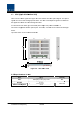
.2.2 2 Block Dia agram of ODU O 4.2.3 3 ODU partts Figure 4.
No o. U Unit Des scription Re emark DO OU 1 DOU Co onvert TX RF F signals into o optical sign nals; Co onvert RX op ptical signals s into RF sign nals; Max 2ea Prrovide up to four optical ports p per DO OU 2W Way Dividerr 2 2W Divide TX RF signals into two; t Co ombine two RX RF signa als into one 3 DU 4 Shelf 5 Accesssories Distribution Unit U Distribute pow wer and signa als to DOU 19 9” rack, 1U 5PIN DSUB, Male to fem male 1pcs 15 RF Coaxial Ca able Assemb bly 2pcs 4.2.
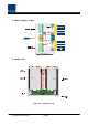
2) 2W Way Divider (2W) 2W iss equipped with w two 2-way splitters in a one-mod dule form an nd the splitters work for TX/RX T signa als, respectivvely. Desig gned in broa adband type, the divider combines an nd divides 2GHz or high her of signals s from FSK modem signals. der Outer Lo ook Figure 4.12 – 2Way Divid 4.2.5 5 Front/rear panels off ODU 1 1) Front pa anel Figure 4.