
User's Manual

Confidential & Proprietary 33/136
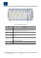
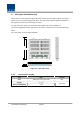
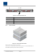
Figure 4.7 – BIU front panel Outer Look
Item Description
1. MDBU LED LED to show whether MDBU is installed and gets faulty
2. RF Monitor Port
20Db Coupling compared with TX Input Level
20Db Coupling compared with RX Output Level
3. Alarm LED & Reset
Communication state with devices, alarm status of the system and reset
switch
4. NMS(RS-232C port)
RS-232C port for communication and diagnosis of devices through
PC/laptop
5. NMS(Ethernet port)
Ethernet port for upper network
This equipment is indoor use and all the communication wirings are
limited to inside of the building
6. Pwr Test Port & ALM Output DC power test port and ALM LED to show abnormal state, if any
7. Power switch Power ON/OFF switch