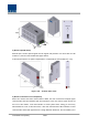
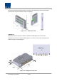
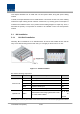
3) Remote Optic(R OPTIC) Remote Optic converts optical signals into RF signals and performs vice versa. With an FSK modem in it, the unit communicates with upper devices. It also has internal ATT for optical compensation to compensate for optical cable loss, if any. Figure 4.28 – R OPTIC Outer Look 4) Remote Central Processor Unit (RCPU) RCPU can monitor and control each module of ROU.
check and control device status through PC and laptop. This equipment is indoor use and all the communication wirings are limited to inside of the building. Figure 4.29 – RCPU Outer Look 5) Multiplexer Multiplexer works as a module to combine or distribute multiple signals into one antenna. This device has a port to combine multiple signals. You need to connect input and output ports of RDU through a corresponding port. Figure 4.
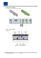
6) System Interface Unit(SIU) SIU distributes power and signals to each module. 4.4.5 Bottom of ROU 1) Functions Figure 4.
Item Description 1. VHF/UHF TX/RX Port Terminal for TX and RX antenna ports of VHF and UHF 2.Antenna Port System Antenna Port, N-type female 3. Power Port AC 120V input port or DC-48V input port 4. Optic Port Optical input port 5.External Port Port for external devices 6.
Section5 System Installation & Operation 5.1 BIU Installation 5.2 ODU Installation 5.3 ROU Installation 5.4 OEU Installation 5.
This chapter describes how to install each unit and optical cables, along with power cabling method. In detail, the chapter describes how to install shelves or enclosuers of each unit, Power Cabling method and Optic Cabling and RF Interface. Furthermore, by showing power consumption of modules to be installed in each unit, it presents Power Cabling budget in a simple way. Then, it describes the quantity of components of modules to be installed in each unit and expansion method. 5.1 BIU Installation 5.1.
to combine and divide TX/RX signals, MPSU to supply devices with power, MCPU to inquire and control state of each module and Power Cable to supply power from external rectifiers. In addition, MDBU can be inserted and removed to provide services for desired band (Optional). 5.1.2 BIU Power Cabling BIU has -48V of input power. This unit should connect DC cable with the Terminal Block seen at the rear of BIU.
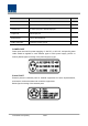
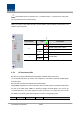
Note that BIU does not operate if the "+" terminal and the "–" terminal of the -48V power are not inserted into the accurate polarity. When you connect -48V power with BIU, use the ON/OFF switch of MPSU located at the front of BIU to check the power. Power Switch LED Abnormal, Not supply Power -48Vdc ON Normal supply power -48Vdc O DC ALM I 5.1.
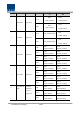
TX 800PS RX 800PS Port #1 TX(851~869MHz) 1 800PS MDBU RX(806~824MHz) Single Band 800PS 800PS Port#2 TX(851~869MHz) RX(806~824MHz) 850C Port #3 850C TX(869~894MHz) RX(824~849MHz) 2 850C MDBU Single Band 850C Port#4 850C TX(869~894MHz) RX(824~849MHz) 1900P 1900P TX(1930~1995MHz) RX(1850~1915MHz) 1900P 1900P TX(1930~1995MHz) RX(1850~1915MHz) 1900P 1900P TX(1930~1995MHz) RX(1850~1915MHz) 1900P 1900P TX(1930~1995MHz) RX(1850~1915MHz) AWS-1 AWS-1 TX(2110~2155MHz) RX(1710~1755MHz)
Port#4 900I TX(929~941MHz) 900I RX(896~902MHz) 700PS 700PS TX(764~776MHz) RX(794~806MHz) 700PS 700PS TX(764~776MHz) RX(794~806MHz) Port#3 850C TX(869~894MHz) 850C RX(824~849MHz) Port#4 850C TX(869~894MHz) 850C RX(824~849MHz) Port#1 Dual Band 850C+700PS 700PS:2Port 6 Port#2 MDBU 850C:2Port At the rear of BIU, input and output ports are seen for each MDBU. The name of all the ports are silk printed as "#1, #2, #3 and #4.
Through spectrum, you need to check signals sent from BTS TX. If the signals exceed input range (-20dBm~+10dBm), you can connect an attenuator ahead of the input port to put the signals in the input range. BIU interface with Bi-Directional Amplifier Basically, BIU is in Simplexer type; when you use BDA, you need to separate BDA signals from TX and RX type. Using a duplexer or a circulator, you can separate TX/RX signals of an external device from each other. Figure 5.
Figure 5.3 – 800PS BDA Interface using Duplexer BIU interfaces with BDA in either of the methods above. In this case, you need to check TX input range as well. Given the TX input range (-20dBm~+10dBm/Total per port), make sure to see if the value is in the input range, using Spectrum Analyzer, when you connect input ports. 5.1.4 MDBU insertion MDBU is designed to let a MDBU inserted into any slot. BIU can be equipped with a total of four MDBUs.
LED Description Power is not supplied. ON Power is supplied. Normal Operation ALM Abnormal Operation MONITOR SMA port seen at the front panel of MDBU enables you to check current level of TX input and RX output signals in current service without affecting main signals. TX MON is -20dB compared with TX Input power and RX MON is -20dB as well compared with RX Output power. 5.1.5 ODU Interface BIU supports up to four ODUs.
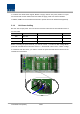
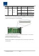
At the rear part of ODU, the number of RF Ports and Signal Ports are printed in order. Therefore, you need to be careful in case of expansion of ODU.
If ODU is not connected in the right order, related devices may fail to communicate with each other or the unit may read wrong information. Given this, you need to connect the unit with accurate RF Port and Signal Port in a corresponding number. For unused RF Ports for ODU expansion, make sure to terminate them using SMA Term. When you put ODU on the top of BIU, it is recommended to install the unit at least 1U apart from BIU. Heat from BIU climbes up to reach ODU. 5.1.