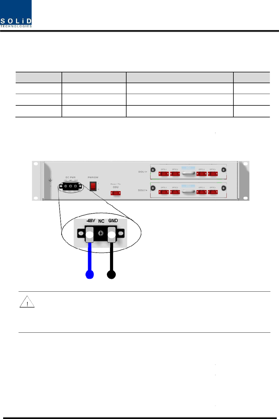
5.4.2 OEU Power Cabling The input power of OEU is DC -48V. 48V. You need to connect DC cable with the Terminal Block seen at the rear of OEU. Terminal -48V NC GND Color of cable Blue color Description Remark Input range: -42 ~ -56Vdc Not Connected Black color Before connecting the power terminal, you need to connect “+” terminal of Multi Voltage Meter probe with the GND terminal and then connect “–“ terminal with -48V 48V to see if “-48Vdc” “ voltage is measured.
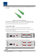
of wavelength (TX:1310nm, RX:1550nm) through one optical core. DOU has SC/APC of optical adaptor type. Figure 5.7 – Optical cable of SC/ACP Type For optical adaptor, SC/APC type should be used. To prevent the optical access part from being marred with dirt, it should be covered with a cap during move. When devices are connected through optical cables, you need to clear them using alcohocol to remove dirt. 5.4.4 Insert DOU to OEU Into OEU Shelf, up to two DOUs can be inserted.
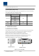
you nedd to install BLANK UNIT into them. 5.4.5 Consumption Power of OEU OEU has -48V DC Power supply in it. ODU can be equipped with up to two DOUs. Depending on the quantity of DOU, power consumption is varied. The following table shows power consumption of OEU: Part Unit Consumption Power Remark Shelf EWDM Common Part 12W ERF EPSU 5.5 OEU_4 DOU 1 EA 23W OEU_8 DOU 2 EA 33W ADD ON ROU Installation 5.5.1 AOR Enclosure installation AOR is designed to be water- and dirt-proof.
Figure 5.9 – Dimension used to install AOR on the WALL ROU Wall Mount Installation Turn M12 Fixing Screws by half on the wall and fully fix the screw with a Wall Mount Bracket on it. For convenience, the Wall Mount Bracket has fixing holes to let you easily mount an enclosure. Turn the M5 Wrench Bolt by half at each side of the Heatsink of the enclosure.
Figure 5.10 – Installation flow diagram when AOR installs on wall Put the enclosure with the M5 Wrench Bolt fixed on the fixing groove and fix the M5 Wrench Bolts into the remaining fixing holes. In this case, you will use 6EA of M5 Wrench Bolts in total except bolts used for the fixing groove. ROU Rack Mount Installation Like other units, AOR is designed to be inserted into a rack. The unit occupies about 4U of space except cable connection.
Figure 5.10 – Installation flow diagram when AOR installs in the rack AOR components AOR has the following components: No.
RF cables - One for interface TX signal with ROU - Another for interface RX signal with ROU 2EA 5.5.2 AOR Power Cabling AOR supports both of DC-48V and AC120V of input power. As PSU for DC-48 and PSU for AC120V are separated from each other, you need to select one of them in case of purchase order. RPSU for DC -48V and RSPU for AC 120V have the same configuration and capacity while each of the units uses different input voltage from each other.
Check if the connection is the same as one seen in the table above and make sure before turn the power ON. If you want to turn on the power of AOR, move PSU’s circuit break switch to “I”status Check if the POWER LED indicator on the AOR PSU is green lights status Information of LED at the front RDU When power of AOR is turned on, LED of the PSU front panel shows the following information: LED Description Power is not supplied ON Power is supplied.
5.5.3 GND Terminal Connection AOR has one GND terminal port where is on rear side, like below - Take off the GND terminal port from enclosure and connect to ground cable, then fix it the position of enclosure again - The he opposite end of the ground cable should connect to the communication GND of building - The he ground lug is designed meeting the SQ22 standard 5.5.
SISO 32W MIMO 50W RDU 700LTEF SISO & MIMO HPA ON 5.5.6 Interface with existing ROU AOR is not operated by themselves. TX/ RX signals receive/transmite through RF port terminal of existing ROU. Also for communication with existing ROU, should connect cable on external port of each other. The following shows the connection diagram with existing ROU: Figure 5.
Figure 5.
Operation 6.1 BIU Operation 6.2 ROU Operation This chapter describes operation of SMDR-NH124. It deals with procedures and operations for normal system operation after installation. It also describes operations per unit and interworking methods.
6.1 BIU Operation 6.1.1 BIU 6.1.2 TX Operation at BIU TX level to be sent to BIU should be in the range of -20dBm 20dBm ~ + 10dBm. If the level exceeds the range, you need to connect an attenuator with the front end of BIU input and adjust the level in the corresponding range. Out of the range, maximal power cannot be outputted and so you need to increase output power of BDA or adjust attenuation amount of BTS’s BTS s coupler or ATT to adjust the level.
After turning on the switch of the power supply in BIU, check information on each module’s LED of the system. The table below shows normal/abnormal cases depending on the status of each module’s LED. LED information Unit LED ON Indicates Green: MDBU is normally power-supplied. Green: MDBU is normal. MDBU ALM Red: MDBU is abnormal; check the alarm through RS-232C. MCPU ON Green: MCPU is normally power-supplied. TXD Green flicker: TX signals are transmitted to communicate with ROU.
Check if MDBU is inserted into a corresponding slot of BIU. The ID screen shows the following: A. MDBU ID: 800Public Safety, 800PS+900I+Paging, 850C, 700PS+850C, AWS-1,1900P AWS B. Not Insert: This status value appears when MDBU has not been set. C. Link Fail: This status value appears when MDBU has been set but it fails to communicate with modules. Use the ON/OFF (Activation/de-activation) (Activation/de activation) function for a port you want to use and turn it ON.
1900PCS 26dBm-10*LOG(N) 4 AWS-1 26dBm-10*LOG(N) 4 VHF 24dBm-10*LOG(N) 1 UHF 24dBm-10*LOG(N) 1 Check if the level of TX IN POWER is the same as the value measured through spectrum (Within ±3dB). Use TX IN AGC function and automatically set internal ATT depending on input level. ATT is automatically set based on -20dBm of input . The table below shows TX IN ATT depending on TX IN POWER. For manual setting, you can set ATT depending on input according to the table.
Use various upper/lower limits. The following table shows recommended limit settings: Item Recommended Limit Remark TX IN HIGH ALM 15dBm Alarm TX IN LOW ALM -25dBm Alarm RX OUT ALC 0dBm Auto Level control RX OUT HIGH ALM 5dBm Alarm As such, when you finish setting normal input levels and alarm limits, check if the value of MODULE FAILUER LED Indicator is lit green (Normal case). 6.1.
setting makes BIU actually try to communicate with lower units while collecting the status value of units. The menu below shows INSTALL menu, where you can see topology for overall units at a glance. Overall topology for SMDR-NH124 SMDR Configuration of BIU-OD ODU-ROU Configuration on whether to use BIU varies depending on the topology above and so you need to check on a unit to be installed. Ex.
1. Select INSTALL from GUI menu. 2. Check on ODU1 menu>DOU1>ROU1. 3. Close the INSTALL menu. 4. Check if ROU is created, which was checked on at the left TREE panel. 6.1.5 ODU Operation at BIU BIU can be equipped with up to four ODUs. One ODU can hold two DOUs in it. For information on insertion/deletion of DOU in ODU, you can see at the main window of BIU.
When you select ODU screen from the left TREE panel, you can see DOU1 or DOU2 menu actiavted depending on whether DOU has been inserted. Then, the optical port set at the INSTALL menu is also actiavted to let you check PD value of the optical port. Any optical port not set at the INSTALL menu is seen de-activated in grey. The level of Laser diode received from ROU/OEU is +7dBm±0.5dB.
In general, the level of optical PD POWER should be +6dBm~ +2dBm±1.5dB. +2dBm 1.5dB. What is more, ODU has the function of automatically compensating for optical cables. The following procedure is related to how to make optical compensation with ROU connected with port, at a corresponding DOU window of ODU: 1. Check if ODU is smoothly communicating with a corresponding ROU. 2. Select ODU or DOU from the left Tree panel. 3. Set “RX OPTIC COMP” COMP of the optical port of a corresponding DOU as "ON." 4.
And it can be installed on a wall or into a rack. Basically, one antenna is provided. To install a variety of antennas, you need such devices as a divider and a coupler. ROU can work with a DC Feeder and an Optic Cable Feeder. For power supply of ROU, a power supply in AC-DC and DC-DC type is provided to let you select a power supply suitable for an application. For upper level, ROU can be connected with ODU and OEU. It has AGC function for 5dBo of optical cable loss.
ALM ON RPSU Normal Operation Abnormal Operation The power is not supplied or the polarity of -48V 48V is reversed. The power is supplied. ID Setting Use an RS-232 232 Cable(Direct Cable) for connection with DEBUG port of ROU RCPU. Execute GUI (Graphic User Interface). When you connect ROU directly with a Serial port, the screen will show the TREE of a direct line of units connected with ROU. Basic ROU ID is i set as ODU1DOU1-ROU1. ROU1. Set it with the ID of a designed ROU.
ROU Optic Comp Operation ROU has the function of automatically compensating for optical loss. It can do the work for up to 5dBo of optical loss. Set “TX TX OPTIC COMP” COMP of ROU as "ON." Optical compensation of ROU can not be made without communication with such units in upper level as ODU or OEU. For 1dBo of optical loss, basic TX OPTIC ATT is 12dB; 12 for 5dBo of optical al loss, TX OPTIC ATT is 4dB. OPTIC COMP works only one time before it stays dormant.
RDU. When you select the tab of a corresponding slot (LEFT, MIDDLE and RIGHT) from the main window of ROU, you can inquire and set the status of a corresponding RDU module. Set HPA of a corresponding RDU as “ON.” Use TX OUTPUT AGS function and set it as a desired output level.
A. Success: The AGS function is normally made. B. Not Opterate OPTIC Comp: Optic Comp is not executed. C. Lack of ATT: There is no attenuation available. Use various upper/lower limits.
6.3 OEU Operation The figure below shows the level of the system link of SMDR-NH124 SMDR (BIU--ODU-OEU-ROU). This section describes OEU-related information. OEU receives various signals through optical modules. The optical signals are converted to RF signal and the RF signal also is amplified to moderate signal level. To o transmit to ROU, the signal is converted to optical signal 6.3.1 OEU Operation OEU is in shelf enclosure type. OEU is located at a remote closet in a building.
module's LED of the system. The table below shows normal/abnormal cases depending on the status of each module's LED.
ID Setting Use an RS-232 232 Cable(Direct Cable) for connection connection with DEBUG port of OEU. OEU Execute GUI (Graphic User Interface). When you connect OEU directly with a Serial port, the screen will show the TREE of a direct line of units connected with OEU. Basic OEU ID is set as ODU1ODU1 DOU1. Set it with the ID of a designed OEU.
Checking Communication LED of OEU Step1 : checking whether communicate with BIU(ODU) Check if TXD1 and RXD2 LEDs in OEU front LED make communication. Receiving FSK signals from BIU, OEU sends requessted status value to BIU. During reception, RXD1 LED flicks. During tramsmission, on the other hand, TXD1 LED flicks. At this time, you need to check if whether to use a corresponding OEU is checked on (See "whether to use BIU OEU/ROU"). Step2 : Checking whether communicate with ROU OEU do as Hub.
3. Communication Fail: Communication with ROU is in poor conditin. If OEU does not make optical compensation, there will will be erors in the budget of system link. It can cause lower output level or make Spurious Emission not satisfying for a standard.
Section7 Additive functions 7.1 Shutdown function 7.2 Total power limit function 7.3 Output power automatic setting function 7.4 Input power AGC function 7.5 Input power limit function 7.
This chapter describes additive functions of SMDR-NH124. 7.1 Shutdown function (TX ( output shutdown) The DAS has an automatic shutdown function to protect the DAS itself and the wireless network when the normal operational conditions cannot be maintained The DAS shut down automatically when the composite power downlink output power is above the values defined as average for the device for a period not to exceed 5seconds.
automatically set to defined level. If AGC logic finished, logic operation results show on the result window of GUI. There are three types of results as follows 1. Success: The AGS function is normally completed. 2. Not Opterate OPTIC Comp: Optic Comp is not executed. 3. Lack of ATT: There is no attenuation available. If normal logic don’t executed, changed ATT return to initial ATT Through output AGC function, can be checked whether optic compensation is executed or not 7.
-10dBm 10dB 7.5 Input power limit function (TX Input ALC) The DAS has TX input ALC function at the BIU to limit level when input power is increased above level by operated input AGC function Normally, there are more than two input port in the MDBU of BIU For example, 850cellular band has two input port to support both VzW and AT&T Two input power may be different each other. The DAS have input attenuator in first stage of MDBU. Through input AGC function, input ATT is adjusted according to input power.
During optical compensation, the Result window shows "Processing" and then a result value. There are three types of results as follows: 1. Success: The optical compensation is normally competed 2. Over Optic Loss: Generated optical loss exceed 5dBo or more. 3. Communication Fail: Communication with ROU is under poor condition.