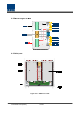
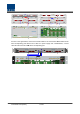
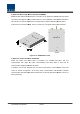
4.2.2 Block Diagram of ODU 4.2.3 ODU parts Figure 4.
No. Unit Description Remark DOU 1 DOU Convert TX RF signals into optical signals; Convert RX optical signals into RF signals; Max 2ea Provide up to four optical ports per DOU 2Way Divider 2 2W Divide TX RF signals into two; Combine two RX RF signals into one 3 DU 4 Shelf 5 Accessories Distribution Unit Distribute power and signals to DOU 19” rack, 1U 15PIN DSUB, Male to female 1pcs RF Coaxial Cable Assembly 2pcs 4.2.
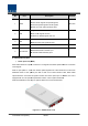
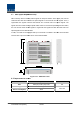
2) 2Way Divider (2W) way splitters in a one-module one module form and the splitters work for TX/RX 2W is equipped with two 2-way signals, respectively. Designed in broadband type, the divider combines and divides 2GHz or higher of signals from FSK modem signals. Figure 4.12 – 2Way Divider Outer Look 4.2.5 Front/rear panels of ODU 1) Front panel Figure 4.
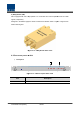
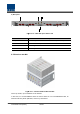
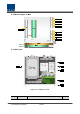
2) Rear panel Figure 4.14 – ODU Rear panel Outer Look Item Description 1. Optic Port SC/APC optical connector terminal; use one optical cable per ROU. 2. DC I/O Port Terminal to deliver power and state values 3. RX RF Port RX RF signal interface terminal 4. TX RF Port TX RF signal interface terminal 4.2.6 Interface with BIU Figure 4.15 – Interface between BIU and ODU On the top of BIU, up to four ODUs can be stacked.
As seen in the figure below, connect the coaxial cable for TX and another coaxial cable for RX with corresponding ports at the rear of BIU. For power supply and communication, connect 15Pin D-Sub Sub Connector cable with a corresponding port.
4.3 OEU (Optic Expansion Unit) OEU is mainly used to remotely deliver signals for Campus clusters. At the upper part, this unit combines with ODU and receives TX optical signals to convert them into RF signals. Then, it regenerates the signals to secure S/N feature and converts them into optical signals. The signals are sent to ROU through optical cables.
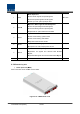
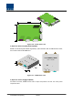
4.3.2 Block Diagram of OEU 4.3.3 OEU parts Figure 4.17 – OEU Inner Look No.
Donor Optic Unit 1 DOU Convert TX RF signals into optical signals; Convert RX optical signals into RF signals; Provide up to four optical ports per DOU Expansion Wavelength Division Multiplexer 2 EWDM Convert TX optical signals into RF signals; Convert RX RF signals into optical signals; Compensate for optical cable loss with ODU Expansion Central Processor Unit 3 ECPU Control and monitoring system status Control and monitoring with RS232 Relay state values of ROU to BIU 4 EPSU Expansion Power Su
2) Expansion Wavelength Division Multiplexer(EWDM) EWDM module makes optical-electronic optical electronic conversion of TX signals and makes electronic-optical electronic conversion of RX signals. With an FSK modem in it, this multiplexer communicates with BIU. It also o has ATT for optical compensation to compensate for optical cable loss between ODUs. Furthermore, it has internal WDM, and so, it needs only one optical cable to work with ROU. Figure 4.
Figure 4.20 – ECPU Outer Look 4) Expansion Radio Frequency Module(ERFM) ERFM reconstructs Signal to Noise degraded by optical modules. With an internal FSK modem, this module communicates with ROU. Figure 4.21 – ERFM Outer Look 5) Expansion Power Supply Unit(EPSU) As DC/DC /DC Converter, EPSU receives -48V 48V of input and provides +9V and +6V of DC power required for OEU.
Figure 4.
4.3.5 Front/rear panels of OEU 1) Front panel Figure 4.23 – OEU front panel Outer Look Item Description 1.EWDM LED LED indicator to check EWDM state to see if it is abnormal 2.DOU LED LED indicator to check DOU module state to see if it is abnormal 3.System LED and Reset Communication state with devices, alarm status of the system and reset switch RS--232C port for communication and diagnosis of devices through 4.