Alliance_eROU User Manual Document Reference: Version: V1.
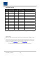
REVISION HISTORY Version Issue Date V 1.0 March 09, 2020 No. of Pages Initials Details of Revision Changes Original Technical Support SOLiD serial numbers must be available to authorize technical support and/or to establish a return authorization for defective units. The serial numbers are located on the back of the unit, as well as on the box in which they were delivered. Additional support information may be obtained by accessing the SOLiD Tehcnology, Inc. website at www.solid.co.
Contents Section1 Safety & Certification Notice ....................................................................... 4 Section2 System configuration and Functions ........................................................... 10 2.1 eROU(edge Remote Optic Unit) ....................................................................... 10 2.1.1 Specifications of eROU .............................................................................. 11 2.1.2 Port on eROU ......................................
Section1 Safety & Certification Notice Confidential & Proprietary 4/19
“Only qualified personnel should handle the DAS equipment. Any person involved in installation or service of the DAS should understand and follow these safety guidelines.” - Obey all general and regional installation and safety regulations relating to work on high voltage installations, as well as regulations covering correct use of tools and personal protective equipment. - The power supply unit in repeaters contains dangerous voltage level, which can cause electric shock.
overvoltage protection device - Only 50 ohm rated antennas, cables and passive equipment shall be used with this remote. Any equipment attached to this device not meeting this standard may cause degradation and unwanted signals in the bi-directional system. All components connected to this device must operate in the frequency range of this device. - Only 50 ohm rated antennas, cables and passive components operating from 150 - 3 GHz shall be used with this device.
- Use of unauthorized antennas, cables, and/or coupling devices not conforming with ERP/EIRP and/or indoor‐only restrictions is prohibited. - Home/ personal use are prohibited. UL/CUL: This equipment complies with UL and CUL 1950-1 Standard for safety for information technology equipment,including electrical business equipment FDA/CDRH: This equipment uses a Class 1 LASER according to FDA/CDRH Rules.
of a type and maximum (or lesser) gain approved for the transmitter by Industry Canada. To reduce potential radio interference to other users, the antenna type and its gain should be so chosen that the equivalent isotropically radiated power (e.i.r.p.) is not more than that necessary for successful communication.
minimum de au moins 50 cm entre la source de radiation (l’antenne) et toute personne physique. Cet appareil ne doit pas être installé ou utilisé en conjonction avec une autre antenne ou émetteur.
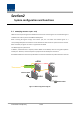
Section2 System configuration and Functions 2.1 eROU(edge Remote Optic Unit) eROU receives TX optical signals from eHUB and converts them into RF signals. The converted RF signal is radiated to the antenna port via the AMP and Multiplexer. When receiving RX signals through the antenna port, this unit filters out-of-band signals in a corresponding Multiplexer and sends the results to OPTIC to make electronic-optical conversion of them. After converted, the signals are sent to a upper device of eHUB.
Figure 2. eROU outer Look 2.1.1 Specifications of eROU Spec.
1900P 43dB AWS13 43dB 700LTE_FN Uplink 2500_100TDD 1900P 45dB AWS13 Input/ Output Impedance 50 ohm 2.6 kg(Internal) Weight 3.0 kg(External) Common Part Power consumption 35W Temperature range -5°C to +50°C Ambient Temperature Humidity Range 5% ~ 90% Non-condensing Sealing (Remote Unit) IEC/UL/CSA 62368-1 IP50 220 x 220 x 90 Integrated Antenna 200 x 200 x 73 External Antenna Size(mm) 2.1.2 Port on eROU 2.1.2.1 Functions Figure 3.
No Port Quantity Remark 1 Optical Port 1EA LC/APC 2 ANTENNA PORT(External Only) 1EA 2.
Section3 System Installation 3.1 eROU Installation The following table shows the required accessories and tools for installing eROU. No Tools Q’ty 1 1 Specification (+), Ø 3.0 Length is more than 20mm Remark For fixing 3.1.1 eROU Enclosure installation The eROU can be mounted on a wall or ceiling. and divided into the version of External Antena and the version of Internal Antena. Figure 4.
Figure 5. Dimension used to install eROU (internal) Figure 3.
3.1.2 eROU(Internal Antenna) Mount Installation_ Case .1 3.1.3 eROU(Internal Antenna) Mount Installation_ Case .
3.1.4 eROU(Internal Antenna) Mount Installation_ Case .3 3.1.
3.1.6 Installation Cable Gland 3.1.6.1 eROU 3.1.6.
3.1.7 Power cabling 1. The eROU receives DC power from the eHub or external adapter. 2. Cable length between eHub and eROU supports up to 2.4 km.(Cable specifications recommend AWG14.) 3. If the maximum length between the eHub and the eROU is exceeded, the use of the External Adapter is recommended. ** Adaptor is extra purchases. Specified below shall be used only adapter. 3.1.8 Ground cabling Not required.