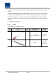
Section5 System Installation 5.
This chapter describes how to install each unit and optical cables, along with power cabling method. In detail, the chapter describes how to install shelves or enclosuers of each unit, Power Cabling method and Optic Cabling and RF Interface. Furthermore, by showing power consumption of modules to be installed in each unit, it presents Power Cabling budget in a simple way. Then, it describes the quantity of components of modules to be installed in each unit and expansion method. 5.1 HROU Installation 5.1.
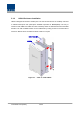
5.1.2 HROU Enclosure installation HROU is designed to be water- and dirt-proof. The unit has the structure of one-Body enclosure. It satisfies water-proof and quake-proof standards equivalent of NEMA4(IP66). The way to install for both HMRU and ARU has same. Basically HROU is attached with wall mountable bracket. This wall moutable bracket can be unattached by loosing screws on the both side of enclosure. HROU can be mounted into either of wall or on a pole. M OUNT BRACKET HOUSING Figure 5.
Figure 5.
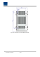
HROU Wall Mount Installation Turn M12 Fixing Screws by half on the wall and fully fix the screw with a Wall Mount Bracket on it. For convenience, the Wall Mount Bracket has fixing holes to let you easily mount an enclosure. Turn the M5 Wrench Bolt by half at each side of the Heatsink of the enclosure. M OUNTING HOLE M OUNT BRACKET 4-M 12 Fixing Screw HOUSING 8-M 8 W rench Bolt Figure 5.
HROU components HROU has the following components: No. Common Part Unit Description Remark Enclosure Including Wall mounting bracket 1EA RCPU - 1EA R_OPTIC With SC/ACP adaptor RPSU AC 120V 1EA - 1EA Power Cable - MS Connector with 4 hole to AC 120 plug(AC) - MS Connector with 3 lug termination(battery) 1EA,option al Each 1EA 1900PCS RDU 44.5 850CEL RDU 44.5 Optional Part RDU 700LTE RDU 44.5 Up to 2EA AWS-1 RDU 44.5 to be 700PS RDU 44.5 mounted 800I/PS RDU 44.5 900I RDU 44.
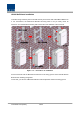
5.1.3 How to expand ARU at the HMRU HMRU can expand ARU up to 3. The three item is needed for connection between HMRU and HARU.
Following picture shows the connection diagrm between HMRU and HARUs For expanding HARU at the HMRU in proper cable length provided, we recommend MRU be located at middle of among ARUs. The cables between HMRU and HARU have each 3m length HM RU HARU1 HARU2 HARU3 Figure 5.4 – Connection diagram between HMRU and HARU Table below shows the point to connect between HMRU and HARU according to ARU order.
5.1.4 HROU Power Cabling AC Power cabling HROU supports only AC120V of input power. Provided outside power cable is only one type. The pin discription of AC port is below. You should connect exact polarity of AC. Port outlook MS Connector numbering Name Description A AC_H AC Hot B AC_N AC Neutral C N.C Not Connected D F.G Frame Ground A : AC_H B : AC_N C : N .C D : F.G Check if the connection is the same as one seen in the table above and make sure to turn the power ON.
5.1.5 HROU Ground cabling The Grounding terminal is located at the right of HROU enclosure fixed by M6 screw. Compression terminal is attached already when is delivered. The best thickness of cable is AWG#6 copper grounding wire Figure 5.5 – Location of Ground Terminal The specification of compression terminal is like below Figure 5.
The required part number is JOCT 14 supporting AWG 6. The way to install the grounding cable comply with below procedures Figure 5.7 – How to install Ground Terminal The procedures are 1. Loosen a two M6 screws and then take compression terminal off 2. Insert AWG#6 Grounding Wire into terminal and then compress a terminal using tool 3. Assemble the terminal which made in step “2” using 2xM6 screws 4.
5.1.6 Optical Cabling HROU makes optical-electronic conversion of TX signals from upper ODU and OEU and makes electronic- optical conversion of RX signals. HROU has one optical module in it. As WDM is installed in the R_OPTIC module, two pieces of wavelength (TX:1310nm, RX:1550nm) can be sent/received with one optical core at the same time. HROU has SC/APC of optical adaptor type. For optical adaptor, SC/APC type can be used only.
The picutre below is wrong intallation diagram Figure 5.9 – Wrong optical port installation method Optical cables should be inserted into Optic Port outside of HROU. In the inside, you go through the fixed devices to fix more tight. At this time, curvature of the optical cable should be in at least 10Ø to prevent optical link margin from adding optical loss. Through GUI, check if PD value of ROPTIC is in a tolerable range (+10~-2dBm).
5.1.7 Mounting of RDU HROU has slots to enable up to two RDU modules to be mounted in it. You can mount a RDU into any slot. It is not possible to provide services with a RDU module alone; you need to connect RDU cavity duplexer antenna port with antenna port of enclosure. Figure 5.
Because there are the guide bar, it assists RDU to move exact location. The screw for fixing RDU on the heat-sink is already attached on RDU and so you can assemble RDU easily. Figure 5.11 – The Guide bar The additive provided accessories with RDU are 4cables like below Figure 5.
For example, How to install XXX RDU 44.5 The provided components of RDU are below. Figure 5.12 – RDU and accessories We provide RDU to extra package from ROU common enclosure. In the empty RDU space, you first mount the RDU at 1st RDU space like below R‐OPTIC RCPU RPSU RSIU Enclosure Figure 5.
Second, connect cables between PSU/SIU and RDU like below We recommend to assemble in order 1. RDU power : 2. RDU RF RX cable 3. RDU I/O : : 4. RDU RF TX cable : ① ② ④ ③ Figure 5.14 – Connection diagram of RDU1 Third, connect RDU’s antenna cable to antenna port of enclosure. 5.
Figure 5.14 – Connection diagram of RDU2 Before it assemble RDU at the ROU enclosure, should turn RDU switch off like below When all connections are completed, should turn RDU switch on At this time, the switch’s direction is at O : the status of turn it off and I : the status of turn it on.
5.1.8 How to mount FAN Unit Fan unit will be delivered without connecting with enclosure because FAN connector is subject to be broken by exteral impact. After you install enclosure, you should mount FAN Unit. FAN CABLE “X” N eed a space “X” for bending the FAN cable RFAN UNIT Figure 5.14 – How to mount FAN Unit The screw for fixing FAN unit is already embedded in the FAN Unit. First, push FAN Unit to designated location of enclosure.
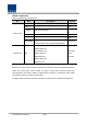
5.1.9 Consumption of HROU The following table shows power consumption of HROU component: Part Unit Consumption Power Remark Enclosure Common Part RCPU HMRU : 50W ROPTIC HARU : 40W RPSU RDUs 1900PCS RDU44.5 350W 850CEL RDU44.5 300W 700LTE RDU44.5 300W AWS-1 RDU44.5 330W 700PS RDU44.5 320W 800I/PS RDU44.5 300W 900I RDU44.5 300W For power consumption of HROU, the common part consumes 50W an 40W at the HMRU and HARU.
Section6 Operation 6.
This chapter describes operation of SMDR-NH124. It deals with procedures and operations for normal system operation after installation. It also describes operations per unit and interworking methods. 6.1 HROU Operation The figure below shows the level of the system link of Alliance DAS (BIU-ODU-HROU). This section describes HROU-related information. HROU receives various signals through optical modules.
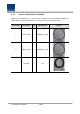
1) Checking the status of HROU's LED Indicator After turning on the switch of the power supply in HROU, check information on each module's LED of the system. The table below shows normal/abnormal cases depending on the status of each module's LED. Unit LED ON Indicates Green: HROU is normally power-supplied. Green: Laser Diode is normal. LD Red: Laser Diode is abnormal. Green: Photo Diode is normal. PD RCPU Red: Photo Diode is abnormal; check optical cables.
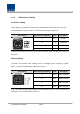
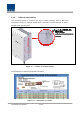
2) ID Setting Connect an RS-232 Cable(Direct Cable) for connection with DEBUG port of HROU RCPU. Execute GUI (Graphic User Interface). When you connect HROU directly with a Serial port, the screen will show the TREE of a direct line of units connected with HROU. Basic HROU ID is set as ODU1-DOU1-HROU1. Set it with the ID of a designed HROU. Before setting an HROU ID, you need to check if HROU is connected with the optical port of ODU or OEU (See System Topology at "Setting whether to use BIU"). Figure 6.
4) HROU Optic Comp Operation HROU(HMRU) has the function of automatically compensating for optical loss. It can do the work for up to 10dBo of optical loss. Set “TX OPTIC COMP” of HROU as "ON." Optical compensation of HROU can not be made without communication with such units in upper level as ODU or OEU. For 1dBo of optical loss, basic TX OPTIC ATT is 24dB; for 10dBo of optical loss, TX OPTIC ATT is 4dB. OPTIC COMP works only one time before it stays dormant.
5) RDU Setting Mount RDUs you want to offer service up to 2 according to the procedurs described at chatper 5. After all cables are connected completely, turn the RDU switch on. Check if the LED become green. Through GUI, check if the ID of RDU module is inquired at 1st band and 2nd band. When you select the tab of a corresponding slot (HMRU, HARU) from the main window of HROU, you can inquire and set the status of a corresponding RDU module. Figure 6.
The table below shows maximally available Composit Powerlevels that can be set per band: RDU Band Composite power Setting range 700PS 44.5dBm 44.5 ~ 19.5dBm 700LTE 44.5dBm 44.5 ~ 19.5dBm 800PS 44.5dBm 44.5 ~ 19.5dBm 850Cellular 44.5dBm 44.5 ~ 19.5dBm 900I+Paging 44.5dBm 44.5 ~ 19.5dBm 1900PCS 44.5dBm 44.5 ~ 19.5dBm AWS-1 44.5dBm 44.5 ~ 19.5dBm AGS function enables you to adjust output power as you like.
6) FAN operation FAN operates each RDU and you can turn it on or off throug FAN on/off. But if FAN Auto En is executing, user can’t control FAN on/off. If you want to turn fan off, first turn FAN Auto En off. Figure 6.7 – Fan information FAN operates two modes, Figure 6.8 – Fan setting window 1. FAN On/OFF A. According to temperature, fan repeats on/off operation. B. FAN On Temp Level : The temperature of turning fan on C. FAN Off Temp Level : The temperature of turning fan off 2.