Hercules‐S (5W Remote Unit) User Manual SOLiD, Inc.
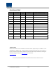
REVISION HISTORY Version Issue Date V 1.0 Oct. 23, 2013 No. of Pages Initials Details of Revision Changes Original Technical Support SOLiD serial numbers must be available to authorize technical support and/or to establish a return authorization for defective units. The serial numbers are located on the back of the unit, as well as on the box in which they were delivered. Additional support information may be obtained by accessing the SOLiD Tehcnology, Inc. website at www.solid.co.
Contents Section1 Safety & Certification Notice ......................................................................... 5 Section2 Introduction ................................................................................................ 8 2.1 Purpose ............................................................................................................. 9 2.2 HERCULES‐S .....................................................................................................
Contents of Figure Figure 3.1 – Remote Unit Block Diagram ............................................................. 12 Figure 3.2 – Inside of Remote Unit ...................................................................... 13 Figure 3.3 – Remote Unit Dimension ................................................................... 15 Figure 4.1 – Exterior of Remote Unit ................................................................... 18 Figure 4.2 – Dimension used to install REMOTE UNIT on the WALL ...
Section1 Safety & Certification Notice Confidential & Proprietary 5/30
“Only qualified personnel should handle the DAS equipment. Any person involved in installation or service of the DAS should understand and follow these safety guidelines.” ‐ Obey all general and regional safety regulations relating to work on high voltage installations, as well as regulations covering correct use of tools and personal protective equipment. ‐ To prevent electrical shock, switch the main power supply off prior to working with the DAS System or Fiber BDA.
If powered directly from the mains distribution system, it shall be used additional protection, such as overvoltage protection device ‐ Only 50 ohm rated antennas, cables and passive equipment shall be used with this remote. Any equipment attached to this device not meeting this standard may cause degradation and unwanted signals in the bi‐directional system. All components connected to this device must operate in the frequency range of this device.
Section2 Introduction 2.1 Purpose 2.
2.1 Purpose HERCULES‐S is a coverage system for in‐building services delivering voice and data in high quality and for seamlessly. As a distributed antenna system, it provides analog and digital phone systems that are served in multiple bands through one antenna. The system covers general public institutions and private facilities. Shopping malls Hotels Campus areas Airports Clinics Subways Multi‐use stadiums, convention centers, etc.
2.2 Signals with a plurality of service provider transmit simultaneously Support multi‐operator in a band Low OPEX / CAPEX Compact design Upgradable design Easy installation and maintenance HERCULES‐S Hercules‐S is one of series of Alliance DAS and has 5W (+37dBm) composite output power every band. RDU that is integrated on package with Duplexer, Power amplifier and RF unit can be mounted up to 5 in the enclosure.
Section3 Functional Description 3.1 General 3.2 Compoent of HERCULES‐S Remote Unit 3.
3.1 General The following figure shows the block diagram of HERCULES‐S Remote Unit. Figure 3.
3.2 Component of HERCULES‐S Remote Unit The following figure shows internal configuration of Remoe Unit with fully RF equipped. Figure 3.2 – Inside of Remote Unit Remote Unit receives TX optical signals from Head‐End and converts them into RF signals. The converted RF signals are amplified through High Power Amp in a corresponding RDU, combined with Multiplexer module and then radiated to the antenna port.
The following table describes components on Remote Unit Unit RDU+BPF x5 RPSU R‐OPTIC RCPU Multiplexer ROU Enclosure Input SIU Output SIU Description Remote Drive Unit Filter and amplify TX signals Filter and amplify RX signals Remove other signals through BPF Remote Power Supply Unit Input power: 120 VAC +/‐ 10% Output power: +29 VDC Remote Optic Make RF conversion of TX optical signals; Convert RX RF signals into optical signals; Compensates optical loss Communicates with BIU/OEU though the FSK mode
3.3 Dimension Figure 3.3 – Remote Unit Dimension ITEM Size(Width, Height, Depth) Weight Power Consumption Operating Temperature Operating Humidity Confidential & Proprietary SPECIFICATION 405 x 960 x 250mm/ 15.94’’ x 37.8’’ x 9.
Section4 System Installation 5.
This chapter describes how to install each unit and optical cables, along with power cabling method. In detail, the chapter describes how to install shelves or enclosuers of each unit, Power Cabling method and Optic Cabling and RF Interface. The needed accessories and tools are list up in the below table.
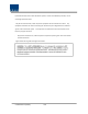
4.1 REMOTE UNIT Installation 4.1.1 REMOTE UNIT Enclosure installation REMOTE UNIT is designed to be water‐ and dirt‐proof. The unit has the structure of One‐Body enclosure. It satisfies water‐proof and quake‐proof standards equivalent of NEMA4. REMOTE UNIT can be mounted on either ceil or the Wall. Basically, REMOTE UNIT has both of a Wall Mount Bracket. The following shows dimension of the fixing point for the Wall Mount Bracket. Figure 4.
Figure 4.
REMOTE UNIT Ceil Mount Installation For horizontal installation, minimum separation distance of 130mm is recommended as shown in the below figure. Figure 4.3 – Horizontal Installation The installation clearance secures system reliability. Select the right location where the remote unit can be installed securely considering weight load capacity, there would be additional mounting structures can be applied as shown in the below figure Figure 4.
4.1.2 Remote Unit Power Cabling Remote Unit supports only AC120V of input power. The following figure shows configuration of power supply for AC 120V. Lug Naming RPSU Terminal naming AC_H AC‐H AC_N AC‐N GND FG Remark The provided connector is “20020517M031B01LF” of FCI vendor. The following table shows main specification of this connector.
In order to install the power connection, first connect HBG‐114‐1 connector(RFS) on hole at bottom of enclosure. This HBG‐114‐1 connector has 36.0mm diameter and made of aluminum. The recommended cable is HYBRIFLEX(HB114‐1‐08U5‐S6F, RFS), which consist SM 6F/O, 5DC pairs and 8AWG. The cable’s outer conductor armor have corrugated aluminum with external jacket made of polyethylence(PE). The outer conductor grounding have a role to eliminate typical grounding requirement and saves on installation costs.
Check if the connection is the same as one seen in the table above and make sure to turn the power ON. CAUTION DOUBLE POLE/NEUTRAL FUSING Ground cable with green/yellow color among 3wires of power cables(HOT, NEUTRAL, GND) should be fixed at heatsink of enclosure before connecting with connector to prevent damage from pulling out by external strong force. At this time, secure M3.5 screw using screw driver with screw type “+“. The recommended AWG is #10.
4.1.3 Remote Unit Optical Cabling REMOTE UNIT makes optical‐electronic conversion of TX signals from upper ODU makes electronic‐ optical conversion of RX signals. REMOTE UNIT has one optical module in it. As WDM is installed in the R_OPTIC module, two pieces of wavelength (TX:1310nm, RX:1550nm) can be sent/received with one optical core at the same time. REMOTE UNIT has SC/APC of optical adaptor type. For optical adaptor, SC/APC type can be used.
4.1.4 GND Terminal Connection The Ground Terminal is located at the lef side of Remote Unit. Grounding must be carried out. Connect an earth‐bonding cable to the grounding connction provided at the outside of the Remote Unit(at left side). After lossening the hex bolt, connect the earth‐bonding cable between the enclosure and hex bolt. Then, fasten all parts again with the hex bolt. Round terminals located on the side of a 0.
4.1.5 Coaxial cable and Antenna Connection The coaxial cables which are connected to antenna distribued network connect to antenna port of REMOTE UNIT. Before connection, check the VSWR value of coaxial cable whether it is within specification using SITEMASTER . At this time, check if the Return loss have above 14dB or VSWR have below 1.
Section5 System Specifications 6.1 Physical Specifications 6.2 RF Performance 6.
5.1 Physical Specifications Parameter RF Connectors Serial Interface connector ROU (1) 7/16 DIN‐type, female (1) RS‐232 9‐pin D‐sub, male (1) SC/APC for ODU Power LED TX LED RX LED LD LED PD LED ALARM LED RESET Button Normal Range: 120VAC 50/60Hz Operating range 108~132V AC, 50/60Hz 390W (ROU w/ 5 RDUs) 405 x 960 x 250mm/ Fiber connector LED Alarm and Status Indicator AC Power Power consumption Enclosure Dimensions (mm) 15.94’’ x 37.8’’ x 9.
5.
5.3 Certification Title Environmental Temperature ange Humidity Range Transportation Standards Remarks ‐25°C to +55°C/ ‐13 to 131°F 0% ~ 90% ETSI EN 300 019‐1‐2 IEC 60721‐3‐2 Ambient Temperature Non‐condensing Class 2.3 Classes 2K2/2M2 Storage ETSI EN 300 019‐1‐1 IEC 60721‐3‐1 Class 1.2 Classes 1K2/1M3 Sealing (Remote IEC 60 529 EN 60 529 IP66 Complaint Unit) Product safety North America UL Certification 60950‐1‐07, 2nd Edition, CSA C22.2 No.