XBee-PRO® 900HP/XBee-PRO® XSC RF Modules XBee-PRO RF Modules Models: XBEE-PRO S3, XBEE-PRO S3B Hardware: S3, S3B 90002173_L 2/4/2014
XBee-PRO® 900HP/XBee-PRO® XSC RF Modules 1. XBee-PRO 900HP RF Module Hardware This manual describes the operation of the XBee-PRO® 900HP RF module, which consists of firmware loaded onto XBee- PRO S3B hardware. XBee-PRO 900HP embedded RF modules provide wireless connectivity to end-point devices in mesh networks. Utilizing the XBee-PRO Feature Set, these modules are interoperable with other devices.
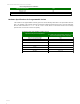
XBee-PRO® 900HP/XBee-PRO® XSC RF Modules XBee-PRO 900HP Specifications Specifications of the XBee-PRO® 900HP/XBee-PRO® XSC RF Module Specification XBee Performance * Indoor/Urban Range 10kbps: up to 2000 ft (610m) 200kbps: up to 1000 ft (305m) * Outdoor RF line-of-sight Range Transmit Power Output 10kbps: up to 9 miles (15.5km) 200kbps: up to 4 miles (6.5km) (with 2.
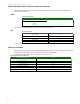
XBee-PRO® 900HP/XBee-PRO® XSC RF Modules XBee-PRO 900HP Serial Communications Specifications XBee RF modules support both UART (Universal Asynchronous Receiver / Transmitter) and SPI (Serial Peripheral Interface) serial connections. UART UART Pin Assignments UART Pins Module Pin Number DOUT 2 DIN / CONFIG CTS / DIO7 RTS / DIO6 12 3 16 More information on UART operation is found in the UART section in Chapter 2.
XBee-PRO® 900HP/XBee-PRO® XSC RF Modules Electrical Specifications for GPIO Pins GPIO Electrical Specification Value Output source current Output sink current 2 mA 2 mA Total output current (for GPIO pins) 48 mA Hardware Specifications for Programmable Variant If the module has the programmable secondary processor, add the following table values to the specifications listed on page 7.
XBee-PRO® 900HP/XBee-PRO® XSC RF Modules XBee-PRO 900HP Pin Signals Mechanical drawings of the XBee-PRO 900HP RF Modules (antenna options not shown). All dimensions are in inches. XBee & XBee-PRO XBee-PW ) (top view) □ . 02 "-" □. SlnraJ ! 6 k Li Jncrr. UrllB* I0.79IW,: PJL N i (2.7gmn) 17 Mm — i- IK . i Pin 10 — _ 7Z . PQimr 2- (I, fr,'4 A . 00fWT..i * .
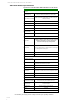
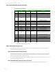
XBee-PRO® 900HP/XBee-PRO® XSC RF Modules XBee-PRO 900HP Mechanical Drawings Pin Assignments for XBee Modules (Low-asserted signals are distinguished with a horizontal line above signal name.) Pin # Name 1 VCC Direction Default State Description Power Supply 2 DOUT/DIO13 Both Output GPIO / UART Data out 3 DIN/nConfig/DIO14 Both Input GPIO / UART Data In 4 DIO12/SPI_MISO Both Output GPIO / SPI slave out 5 nRESET Input Module Reset. Drive low to reset the module.
All unused pins should be left disconnected. All inputs on the radio can be pulled high or low with 40k internal pull-up or pull-down resistors using the PR and PD software commands. No specific treatment is needed for unused outputs. For applications that need to ensure the lowest sleep current, unconnected inputs should never be left floating. Use internal or external pull-up or pull-down resistors, or set the unused I/O lines to outputs.
XBee-PRO® 900HP/XBee-PRO® XSC RF Modules XBee-PRO® 900HP/XBee-PRO® XSC RF Modules © 2014 K-l
Appendix A: Agency Certifications for S3B Hardware Please note that both Appendix B and Appendix C contain Agency Certification information. Please refer to the Preface for instructions on which appendix applies to your product. FCC (United States) Certification The XBee-PRO® 900HP/XBee-PRO® XSC RF Module complies with Part 15 of the FCC rules and regulations. Compliance with the labeling requirements, FCC notices and antenna usage guidelines is required.
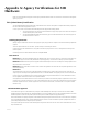
The Omni-directional antenna below has been approved for use with this module when installed into the host device (Host Device FCC ID: 2AQWE-GC170424). The antenna Gain with Cable loss is less than 6dBi. FCC-approved Antennas A WARNING: This device has been tested with Reverse Polarity SMA connectors as below. When integrated into OEM products, fixed antennas require installation preventing end-users from replacing them with non-approved antennas.