
Hardware Description


XBee-PRO® 900HP/XBee-PRO® XSC RF Modules
© 2014
4
XBee-PRO 900HP Serial Communications Specifications
XBee RF modules support both UART (Universal Asynchronous Receiver / Transmitter) and SPI (Serial Peripheral
Interface) serial connections.
UART
More information on UART operation is found in the UART section in Chapter 2.
SPI
For more information on SPI operation, see the SPI section in Chapter 2.
GPIO Specifications
XBee RF modules have 15 GPIO (General Purpose Input/Output) ports available. The exact list will depend on the module
configuration, as some GPIO pins are used for purposes such as serial communication.
See GPIO section for more information on configuring and using GPIO ports.
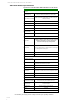
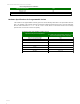
UART Pin Assignments
UART Pins
Module Pin Number
DOUT
2
DIN / CONFIG
3
CTS / DIO7
12
RTS / DIO6
16
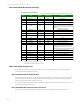
SPI Pin Assignments
SPI Pins
Module Pin Number
SPI_SCLK / DIO18
18
SPLSSEL / DIO17
17
SPI_MOSI / DIO16
11
SPI_MISO / DIO15
4
SPI_ATTN / DIO1
19
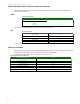
Electrical Specifications for GPIO Pins
GPIO Electrical Specification
Value
Voltage - Supply
2.1 - 3.6 V, (3.0V or higher required for optimal performance)
Low Schmitt switching threshold
0.3 x Vdd
High Schmitt switching threshold
0.7 x Vdd
Input pull-up resistor value
40 kQ
Input pull-down resistor value
40 kQ
Output voltage for logic 0
0.05 x Vdd
Output voltage for logic 1
0.95 x Vdd