444 / 450 Operating manual Mistblower Important: Read this instruction manual carefully before putting the chain saw into operation and strictly observe the safety regulations! 9 450 110 english 01/2008
Preface Symbols Dear Customer, We congratulate you on your new SOLO Mistblower and hope that you will be satisfied with this modern tool. A state-of-the-art single cylinder two-cycle engine with Nikasil coated cylinder bore combined with renowned SOLO technology of high performance with low fuel consumption will guarantee a high degree of application value of this product. Read this operating manual carefully before using the machine for the first time and at all times, strictly observe all safety rules.
Index Page 1. Important Components / Type plate ....................................................................................................... 4 2. Technical Specifications ......................................................................................................................... 6 3. Safety regulations .................................................................................................................................... 7 3.1 Correct use / Notes for General Use 7 3.
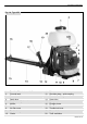
Important Components 1. Important Components / Type plate Fig.
Important Components Fig. 1b, Type 450 1. 2. 3. 4. 5. 6. 7. 8. 9. 10. Tank lid / Filler basket with filter Formula tank Formula outlet Spark plug Carburetor adjustment screws Muffler Starter handle Air filter cover Fuel tank cap Choke 11. 12. 13. 14. 15. 16. 17. 18. 19. 20.
Technical Specifications 2.
Safty regulations 3. Safety regulations 3.1 Correct use / Notes for General Use • • • • • • The mistblower is suitable for the application of crop protection products which have been approved by the responsible, local Registration Authority. The output quantity can depend on the position of the spray tube. If the spray tube is held upwards at an angle exceeding 30 deg. from the horizontal position, the installation of a liquid booster pump may be necessary. The booster pump is available as an accessory.
Maintenance and Care 4. Maintenance and Care 4.1 General Maintenance Hints After a running in period of approx. 5 hours, all accessible screws and nuts (except for carburetor mixture adjustment needles) have to be checked and re-tightened if required. Any service jobs, other than those described in this manual, should only be carried out by an authorized service center. • Any cleaning, maintenance or repair jobs should only be performed when the engine is stopped and with removed spark plug cap.
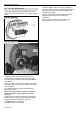
Maintenance and Care 4.3 Spark Plug The carburettor has 3 adjusting screws: The correct spark plug with thermal range 200 is available under the following brands: • Idling end-stop screw "T" • Low speed mixture screw "L" • High speed mixture screw "H" BOSCH CHAMPION WSR6F RCJ-6Y or similar The correct electrode gap is 0.5 mm. Check the plug after every 50 operating hours and replace if electrodes are worn. 4.4 Preparation for Storage Store the motorized mistblower in a dry room.
Maintenance and Care 4.6 Air Filter Maintenance The air filter separates and retains dirt before the air reaches the combustion chamber. This reduces engine wear. Fig. 3a, Type 444 Fig. 3b, Type 450 Regular maintenance increases engine life. Clogged air filters cause performance loss and increased fuel consumption. This leads to a higher toxin level in the exhaust gas and also makes starting more difficult. When the machine is used all day, the air filter should be cleaned daily.
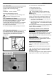
Assembly 5. Assembly Fig. 4 Completely assembly the mistblower before its first use: 5.1 Assembly of misting equipment Attach the blower elbow (1) to the blower housing and secure with both screws (Fig.4D; A+B). Ensure the elbow can swivel easily. Push pleated hose onto blower elbow and secure with clamp (4). 5.2 Assembly of handle, spray tube and spray nozzle Push handle (5) onto spray tube (start from the front) and fix in the required position (Fig.4C).
Starting / Stopping the engine 6. Starting / Stopping the engine Starting with cold engine Fig. 5 • Close choke with choke lever. • Press primer several times until fuel is visible in the primer. • Place your left hand on the formula tank of the mistblower. Hold the starter handle (Fig. 1.Pos. 7) with your right hand and pull the handle up slowly until resistance is felt. Then pull up firmly and rapidly until the engine ‘fires’.
Operating Hints 7. Operating Hints Before every use and before every start of the mistblower check and ensure the machine is in good and safe condition. (throttle operation, ignition switch, safety devices, shoulder strap and check for fuel leaks). • During the starting procedure and while operating the mistblower, the operator must have secure footing and have a safe body position. • The engine starting site should be at least 3 meters away from the refueling site. 7.
Operating Hints Wide-range nozzle (7): Fig. 9 When spraying plants and trees we recommend fixing the wide-range nozzle (7) onto the red standard nozzle (4). This ensures that a large area can be sprayed at one time. Push the wide-range nozzle onto the standard nozzle, until the bead engages. In narrow spaces and for aftercare, we recommend placing the wide-angle grille (7a) onto the wide-range nozzle.
Operating Hints Should the actual value be too high, the metering body may be worn or damaged. In that case, replace the metering body with a new one (part no.:40 74 165). When using accessory sets (liquid pump part no.: type 444 Î 44 00 114, type 450 Î 44 00 235 or ULV accessory, part no.: 49 00 479) a strainer will be integrated into the tank connector. In that case, an incorrect flow rate can also be due to a contaminated or worn strainer. Clean or replace the contaminated/worn strainer (part no.
Maintenance Plan Carburettor Check idling speed X Clean X X Replace Spark plug before spray season X Adjust idling speed Air filter as required after every 50 hors work after the first 5 hours weekly Implement all maintenance jobs regularly. If required, authorise a specialist service centre to maintain the machine for you.
Motorised sprayer - accessories ; For USA only: ECW Statement / Manufacturers Warranty Coverage 9. Motorised sprayer - accessories Part no. Dual nozzle For extending the spray width or for simultaneous spraying of two rows of plants 49 00 137 ULV nozzle 49 00 479 ULV metering equipment 49 00 169 Liquid pump type 444 44 00 114 Liquid pump type 450 44 00 235 Extension wand, 60 cm Multiples can be combined in conjunction with the liquid pump 49 00 333 incl.
Made in Germany SOLO Postfach 60 01 52 D 71050 Sindelfingen Tel. 07031-301-0 Fax 07031-301-130 info@solo-germany.com SOLO P.O.Box 60 01 52 D 71050 Sindelfingen Germany Phone+49-7031-301-0 Fax +49-7031-301-149 export@solo-germany.