
Operation Manual
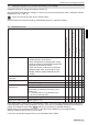


5 Maintenance, cleaning and storage
ENGLISH 10
5.3 Changing the spray nozzle and the
filter element
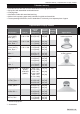
Only the spray nozzles listed in section 10 and the
genuine filter element (part no.: 40 74 922 25,
mesh aperture: 0.8 mm [0.031"]) must be used in
this pressure sprayer.
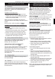
Spray nozzle and filter element must only be
changed if the device is depressurised.
Depressurise the device by pulling on the pressure
relief valve (Fig. 3).
Before pulling on the pressure relief valve (4), the
device must always be in an upright position.
Attention: Keep the device away from your face!
Changing the spray nozzle or the filter element:
x Rinse the nozzle attachment with clean water.
x Disassemble the nozzle attachment (Fig. 2).
x Clean the O-rings, the filter element and the
spray nozzle with clean water and a soft brush.
Never use your mouth to blow through the spray
nozzle! Never use hard objects to clean the
nozzles!
x Replace the previous nozzle by the new one or
the previous filter element by the new one.
x Reassemble the components of the nozzle
attachment (Fig. 2).
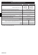
5.4 Greasing the cap gasket
Fig. 10:
For proper sealing of the
spraying agent tank, the
cap gasket (10) must be
well greased with silicone
grease.
5.5 Greasing the pump piston sealing ring
If the pump is hard to operate, the sealing ring of
the pump piston (Fig. 7, pos. 11, part
no.: 00 62 264) should be greased with silicone
grease or replaced if necessary.
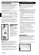
Disassembly of the pump and greasing the
sealing ring:
Fig. 4: Ensure the sprayer is empty and not
pressurised. Place sprayer securely on level
ground. If the pump is completely screwed onto the
tank, loosen the pump with 1–2 turns.
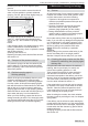
Fig. 5: Firmly hold the pump handle with both
hands and push downwards until the pump
releases from the flange housing with an audible
click. Unscrew the red flange housing from the
sprayer and remove the pump from the tank.
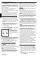
Fig. 6: Use a screwdriver to lever both black flange
semi-circles from the pump cylinder. The pump
piston can now be pulled from the pump cylinder.
Fig. 7: The sealing ring (11) can now be re-greased
with silicone grease or replaced if damaged.
Assembly:
Fig. 8: Place the red flange housing correctly on
the pump piston.
Push the pump piston into the pump cylinder.
Push both black flange semi-circles onto the pump
cylinder until they lock with an audible click.
Fig. 9: Place the pump cylinder securely on level
ground. Line up the red flange housing in the exact
position and firmly push the red flange housing
down with both hands onto the pump cylinder until
the parts lock together with an audible click.
5.6 Draining the spraying agent tank and
cleaning the spraying agent carrying
parts
Before opening the spraying agent tank and before
disassembling the nozzle attachment, depressurise
the device by pulling on the pressure relief valve
(Fig. 3).
Before pulling on the pressure relief valve (4), the
device must always be in an upright position.
Attention: Keep the device away from your face!
Drain the spraying agent tank and all other
spraying agent carrying parts daily after use and
particularly at the end of the spraying season and
thoroughly flush them with clean water.
Any unused spraying agent that is left over in the
device could cause corrosion and hence damage
the device. Special attention must be paid to
wearing parts like spray nozzles, filters and seals.
Please read and observe the cleaning instructions
supplied with the spraying agent.
Recommendation: Use the special SOLO cleaner
for plant protection sprayers (dosing bottle of
500 ml [approx. 16.9 oz], part no.: 49 00 600).
Never use aggressive, acid- or solvent-containing
cleaning agents (gasoline for example).
After cleaning, leave the spraying agent tank open
to dry.
Cleaning the spray nozzle and the filter element:
x Rinse the nozzle attachment with clean water.
x Disassemble the nozzle attachment (Fig. 2).
x Clean the O-rings, the filter element and the
spray nozzle with clean water and a soft brush.
Never use your mouth to blow through the spray
nozzle! Never use hard objects to clean the
nozzles!
x Reassemble the components of the nozzle
attachment (Fig. 2).