Eddy- ZB v1.0 USER Guide Version: 1.0 2013.05.
Eddy-ZB User Guide Revision History Revision Date Document Version Pages May. 13. 2013 1.0 All Description Initial release Copyright 2013 SystemBase Co., Ltd. All rights reserved. Website http://www.sysbas.com/ Tel. +82-2-855-0501 Fax. +82-2-855-0580 16F Daerung, Post Tower-1, 212-8, Guro-dong, Seoul, Republic of Korea If you have any questions, please contact us at www.solvline.com.
Eddy-ZB User Guide Index 1. Preface ............................................................................................................................................ 4 2. Feature ............................................................................................................................................ 4 3. Specification ................................................................................................................................... 4 4.
Eddy-ZB User Guide 1. Preface Thank you for purchasing product by SystemBase. This product has passed thorough quality control and during the 5 years warranty period, the customers can receive free repair services from the day the purchase was made. If you have any questions or difficulties with this product please contact our Technical Support by submitting an inquiry at http://www.solvline.com. 2. Feature Eddy-ZB v1.0 is a module that can be attached to the connectors in Eddy-CPU v2.
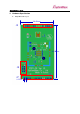
Eddy-ZB User Guide 4. Hardware Specification A. Eddy-ZB Board Layout 28.00mm 16 J1 1 45.20mm 0 1 2 9 10 J5 J7 1.
Eddy-ZB User Guide B.
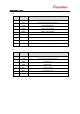
Eddy-ZB User Guide J1 Pin No Name Description 1-3 NC Not Connected 4 3V3 3V–3.6V power-supply connection 5 P0_0 Port 0.0 Digital I/O 6 RXD#1 UART1 Receive Data 7 TXD#1 UART1 Transmit Data 8 CTS#1 UART1 Clear To Send 9 RTS#1 UART #1 Request to Send Signal 10 P0_1 Port 0.1 Digital I/O 11-16 NC Not Connected Pin No Name Description 1 GND Ground 2 3V3 3V–3.
Eddy-ZB User Guide J7 Pin No Name Description 1 R0_7 Port 0.7 Digital I/O 2 R0_6 Port 0.6 Digital I/O 3 DTR#1 UART1 Data Terminal Ready 4 DSR#1 UART1 Data Set Ready 5 -6 3V3 3V–3.6V power-supply connection 7 BHDM USB differential data minus 8 BHDP USB differential data plus 9 RXD#2 UART2 Receive Data 10 TXD#2 UART2 Transmit Data 11 NRST Reset(active-low) 12 - 13 GND Ground 14 - 16 WPID[0:2] Product ID only used by the manufacturer. Please do not work on these pins.
Eddy-ZB User Guide C.
Eddy-ZB User Guide 5. ZigBee Network Configuration If necessary, Eddy-CPU/ZigBee v1.0 can be set and used as an end device, a coordinator, or a router. The ZigBee end device is located at the end of the ZigBee network which can only connect to ZigBee coordinator or ZigBee router. Existing only one network PAN, the ZigBee coordinator manages each devices in the network when ZigBee network is first formed. Expansion of the network is done by ZigBee router.
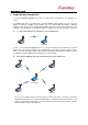
Eddy-ZB User Guide C. Expanding the network by using a router End Device Router Router Coordinator End Device End Device Router End Device When routers are used, 1:1 star type connection by one coordinator can be expanded to a tree type or mesh ZigBee network structure. This can prevent a bottleneck issue where the data is concentrated to one node and detour traffic when there is a network connection problem from some paths.
Eddy-ZB User Guide 6. Commands When following commands are used to modify the values, reset command(ATSR) or rebooting by turning off and then on the unit are require to apply the changed values. A. Command Format The format of all the commands are as follows. Syntax “AT” + Command 2Bytes B. + 2Bytes Values + even Bytes Carriage Return: 1Bytes How to use the commands Select Serial Port, then set baud rate, data, parity, stop, and flow control values. Set as shown below.
Eddy-ZB User Guide D. Commands for ZigBee network The followings are the commands to set ZigBee network.
Eddy-ZB User Guide E.
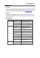
Eddy-ZB User Guide 7. LED LED Status RDY (Green) Blink Link (Red) Meaning Normal Operation Off System Error ON Network Connection Complete (For a coordinator, automatically on) Blink Off Search for target devices and attempts network connection Connection Fail All devices except the coordinator will search for target devices using destination ID. When the connection is made, the link LED will be on and stay on.
Eddy-ZB User Guide 8. Appendix A. Ordering Information Ordering information for Eddy series are shown below. Product Version Description Eddy-CPU 2.1 Embedded CPU Module Eddy-CPU 2.5 Embedded CPU Module Eddy-DK 2.1 Eddy V2.1 Development Kit Eddy-S4M 2.1 Embedded CPU Module (Mini PCI Type) Eddy-S4M 2.5 Embedded CPU Module (Mini PCI Type) Eddy-S4M-DK 2.1 Eddy-S4M v2.1 Development Kit Eddy-S4M-JIG 2.1 Eddy-S4M v2.1 JIG Board Eddy-WiFi 3.0 802.11 b/g/n Wi-Fi Module Eddy-BT 2.