MultiPort PCI Express English Hardware Manual 2012.11.14 Version 1.
Revision History Revision History Revision Date Version Pages Description 02/19/2010 1.0 All Created 05/06/2010 1.1 All Renewal 08/26/2010 1.2 Partial Add New Product 06/27/2011 1.3 All Renewal 10/13/2011 1.4 Partial Add New Product 03/16/2012 1.5 Partial Add New Product 05/17/2012 1.6 Partial Add New Product 09/05/2012 1.7 Partial Add New Product 11/14/2012 1.8 Partial Add New Product Copyright 2006 SystemBase Co., Ltd. All rights reserved.
Contents Contents Greetings from CEO ...................................................................................................................... 5 About MultiPort .............................................................................................................................. 6 Strength of MultiPort ...................................................................................................................... 7 About PCI Express ...............................................
Contents - Product Specifications........................................................................................................ 55 - RS232 Model ..................................................................................................................... 56 - COMBO Model .................................................................................................................. 57 Multi-8C/PCIe Ver1.2 ...................................................................................
Greetings from CEO Greetings from CEO We appreciate all the customers for their deep interest in our products. SystemBase has been engaged wholly in the field of the serial communications to produce the various products related to the same since it was founded in 1987. Along with the recent booming market trend by the advanced skill of high speed communication applying LAN the applicable field of this serial communications could not draw the attention of the public.
About MultiPort About MultiPort MultiPort is a multi serial communication device which makes PC to a multi-user or Multi device system by applying it. Multi-user system or RAS(Remote Access System) is a system which enables a server computer to be used together by multi users thru the terminal at distance or to have the information used together.
Strength of MultiPort Strength of MultiPort The merit of MultiPort is easy and economic to install and maintain. Meantime LAN has high speed to transmit data, but the more devices connected and users are involved the more crashes among the transmitted data happens. Once such crashes happens far more times than some level then the transmitting efficiency is declined suddenly.
About PCI Express About PCI Express PCI Express (Peripheral Component Interconnect Express), officially abbreviated as PCIe is a computer expansion card standard designed to replace the older PCI, PCI-X, and AGP standards. PCIe 2.1 is the latest standard for expansion cards that is available on mainstream personal computers.
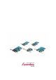
Synopsis Synopsis SystemBase MultiPort PCIe boards are installed on a PCIe slot of your PC, providing 1, 2, 4, 8 serial ports. Each port complies with standard UART for both-way communication at up to 921.6kbps. MultiPort PCIe board occupies one interrupt number (IRQ) and many I/O addresses. MultiPort PCIe board has automatic setting functions that eliminate the inconvenience of manually setting I/O base addresses and IRQ numbers.
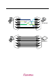
Connectivity Method Connectivity Method RS232 How to connect to a Terminal DCD DSR RXD RTS TXD CTS DTR RI GND 1 6 2 PC 7 3 8 4 9 5 DCD DSR RXD RTS TXD CTS DTR RI GND 1 6 2 7 Terminal 3 8 4 9 5 How to connect to a Modem 1 6 2 7 PC 3 8 4 9 5 DCD DSR RXD RTS TXD CTS DTR RI GND DCD DSR RXD RTS TXD CTS DTR RI GND 1 6 2 7 3 Modem 8 4 9 5 10
Connectivity Method RS422 Point-to-Point Mode Connection 1 1 6 6 2 7 PC 3 8 RX+ RXTX+ TX- RX+ RXTX+ TX- 2 7 3 8 4 4 5 5 9 9 Multi-Drop Mode Connection 1 1 6 2 7 PC 3 8 RX+ RXTX+ TX- RX+ RXTX+ TX- 6 2 7 3 Device 1 8 4 4 5 5 9 9 1 RX+ RXTX+ TX- 6 2 7 3 8 4 9 5 ※ Please check your device Pin Spec 11 Device 2
Connectivity Method 12
Connectivity Method RS485 Connectivity Method 1 1 2 2 6 6 7 PC 3 8 TRX+ TRX- TRX+ TRX- 7 3 Device 1 8 4 4 5 5 9 9 1 6 2 TRX+ TRX- 7 3 8 4 9 5 13 Device 2
Connectivity Method 14
Termination Resistor Termination Resistor What is Termination Resistor? Termination Resistor purpose to reduce of reflection wave in network. We use 120 Ω resistor in RS422/RS485 communication.
Termination Resistor RS485 Mode 1 1 2 2 6 6 7 PC 3 8 TRX+ TRX- TRX+ TRX- 7 3 Device 1 8 4 4 5 5 9 9 1 6 2 TRX+ TRX- 7 3 8 Device 2 4 9 5 16
Multi-1/LPCIe Ver1.2 Multi-1/LPCIe Ver1.2 Multi-1/LPCIe Ver1.2 board is a model that supports PCIe Base Spec 2.0. It is an asynchronous single port product designed to automatically set I/O address and IRQ number when ROM bios or the operating system starts. Multi-1/LPCIe Ver1.2 not only supports maximum communication speed of 460.8Kbps but also provides advanced ability to automatically control IO signals when it is used with driver provided by SystemBase.
Multi-1/LPCIe Ver1.2 - RS232 Model 1.
Multi-1/LPCIe Ver1.2 2. External Power Supply Jumper Setting RI: Do not supply external power and use pin 9 for RI signal line (Default) +5V: Use pin 9 for supplying +5V external Power. +12V: Use pin 9 for supplying +12V external Power.
Multi-1/LPCIe Ver1.3 Multi-1/LPCIe Ver1.3 Multi-1/LPCIe Ver1.3 board is a model that supports PCIe Base Spec 2.0. It is an asynchronous single port product designed to automatically set I/O address and IRQ number when ROM bios or the operating system starts. Multi-1/LPCIe Ver1.3 not only supports maximum communication speed of 921.6Kbps but also provides advanced ability to automatically control IO signals when it is used with driver provided by SystemBase.
Multi-1/LPCIe Ver1.3 - RS232 Model 1. 9 Pin Connector (Male) 2. External Power Supply th Using this function, you can supply Power to outside used 9 pin. If you want to supply power using communication line for barcode reader, use this function.
Multi-1/LPCIe Ver1.3 3. External Power Supply Jumper Setting RI: Do not supply external power and use pin 9 for RI signal line (Default) +5V: Use pin 9 for supplying +5V external Power. +12V: Use pin 9 for supplying +12V external Power.
Multi-1/LPCIe Ver1.3 - COMBO Model 1.
Multi-1/LPCIe Ver1.3 2. Select RS422/RS485 Interface 422: Select RS422 interfcae (Default) 485: Select RS485 interface.
Multi-1/LPCIe Ver1.3 3. External Power Supply th Using this function, you can supply Power to outside used 9 pin. If you want to supply power using communication line for barcode reader, use this function.
Multi-1/LPCIe Ver1.3 4. Jumper Setting for External Power Supply (COMBO) NONE: Do not supply external power and use pin 9 (Default) +5V: Use pin 9 for supplying +5V external Power. +12V: Use pin 9 for supplying +12V external Power.
Multi-1/LPCIe Ver1.3 5. Termination Resistor NONE: Do not install termination resistor. (Default) 422: Install RS422 termination resistor. 485: Install RS422 termination resistor.
Multi-1/LPCIe Ver1.3 6. Slew Rate Limit 10M: Not use Slew Rate Limit ability. Maximum communication speed 921.6Kbps in this mode. 250K: Use Slew Rate Limit ability. Communication speed is limited under 250Kbps. Slew Rate Limit allows communication without errors by activating slew-rate driver to reduce reflection waves and EMI electromagnetic waves. However, communication speed is limited when it is used.
Multi-2/PCIe Ver1.2 Multi-2/PCIe Ver1.2 Multi-2/PCIe Ver1.2 board is a model that supports PCIe Base Spec 2.0. It is an asynchronous single port product designed to automatically set I/O address and IRQ number when ROM bios or the operating system starts. Multi-2/PCIe Ver1.2 not only supports maximum communication speed of 921.6Kbps but also provides advanced ability to automatically control IO signals when it is used with driver provided by SystemBase.
Multi-2/PCIe Ver.1.2 - RS232 Model 1. 9Pin Connector (Male) 2. External Power Supply th Using this function, you can supply Power to outside used 9 pin. If you want to supply power using communication line for barcode reader, use this function.
Multi-2/PCIe Ver1.2 3. External Power Supply Jumper Setting RI: Do not supply external power and use pin 9 for RI signal line +5V: Use pin 9 for supplying +5V external Power. +12V: Use pin 9 for supplying +12V external Power.
Multi-2C/LPCIe Ver.1.2 Multi-2C/LPCIe Ver1.2 Multi-2C/LPCIe Ver1.2 board is a model that supports PCIe Base Spec 2.0. It is an asynchronous single port product designed to automatically set I/O address and IRQ number when ROM bios or the operating system starts. Multi-2C/LPCIe Ver1.2 not only supports maximum communication speed of 921.6Kbps but also provides advanced ability to automatically control IO signals when it is used with driver provided by SystemBase.
Multi-2C/LPCIe Ver1.2 - RS232 Model 1. 9 Pin Connector (Male) 2. External Power Supply th Using this function, you can supply Power to outside used 9 pin. If you want to supply power using communication line for barcode reader, use this function.
Multi-2C/LPCIe Ver.1.2 3. External Power Supply Jumper Setting RI: Do not supply external power and use pin 9 for RI signal line (Default) +5V: Use pin 9 for supplying +5V external Power. +12V: Use pin 9 for supplying +12V external Power.
Multi-2C/LPCIe Ver1.2 - COMBO Model 1.
Multi-2C/LPCIe Ver.1.2 2. Select RS422/RS485 Interface RS422: Select RS422 interfcae (Default) RS485: Select RS485 interface.
Multi-2C/LPCIe Ver1.2 3. External Power Supply th Using this function, you can supply Power to outside used 9 pin. If you want to supply power using communication line for barcode reader, use this function.
Multi-2C/LPCIe Ver.1.2 4. Jumper Setting for External Power Supply (COMBO) NONE: Do not supply external power and use pin 9 (Default) +5V: Use pin 9 for supplying +5V external Power. +12V: Use pin 9 for supplying +12V external Power.
Multi-2C/LPCIe Ver1.2 5. Termination Resistor NONE: Do not install termination resistor. (Default) 422: Install RS422 termination resistor. 485: Install RS422 termination resistor.
Multi-2C/LPCIe Ver.1.2 6. Slew Rate Limit 10M: Not use Slew Rate Limit ability. Maximum communication speed 921.6Kbps in this mode. 250K: Use Slew Rate Limit ability. Communication speed is limited under 250Kbps. Slew Rate Limit allows communication without errors by activating slew-rate driver to reduce reflection waves and EMI electromagnetic waves. However, communication speed is limited when it is used.
Multi-4/LPCIe Ver1.2 Multi-4/LPCIe Ver1.2 Multi-4/LPCIe Ver1.2 board is a model that supports PCIe Base Spec 2.0. It is an asynchronous single port product designed to automatically set I/O address and IRQ number when ROM bios or the operating system starts. Multi-4/LPCIe Ver1.2 is used with Panel-4 VA2 panel. It not only supports maximum communication speed of 921.6Kbps but also provides advanced ability to automatically control IO signals when it is used with driver provided by SystemBase.
Multi-4/LPCIe Ver.1.2 - RS232 Model 1.
Multi-4/LPCIe Ver1.2 - COMBO Model 1. 9 Pin Connector (Female) 2.
Multi-4/LPCIe Ver.1.2 3. Panel Jumper Setting 1) Terminator Installation NONE: Do not install termination resistor. (Default) 422: Install RS422 termination resistor. 485: Install RS422 termination resistor.
Multi-4/LPCIe Ver1.2 2) Slew Rate Limitation 10M: Not use Slew Rate Limit ability. Maximum communication speed 921.6Kbps in this mode. 250K: Use Slew Rate Limit ability. Communication speed is limited under 250Kbps. Slew Rate Limit allows communication without errors by activating slew-rate driver to reduce reflection waves and EMI electromagnetic waves. However, communication speed is limited when it is used.
Multi-4C/LPCIe Ver.1.2 Multi-4C/LPCIe Ver1.2 Multi-4C/LPCIe Ver1.2 board is a model that supports PCIe Base Spec 2.0. It is an asynchronous single port product designed to automatically set I/O address and IRQ number when ROM bios or the operating system starts. Multi-4C/LPCIe Ver1.2 not only supports maximum communication speed of 921.6Kbps but also provides advanced ability to automatically control IO signals when it is used with driver provided by SystemBase.
Multi-4C/LPCIe Ver1.2 - RS232 Model 1. 9 Pin Connector (Male) 2. External Power Supply th Using this function, you can supply Power to outside used 9 pin. If you want to supply power using communication line for barcode reader, use this function.
Multi-4C/LPCIe Ver.1.2 3. External Power Supply Jumper Setting th Using this function, you can supply Power to outside used 9 pin. If you want to supply power using communication line for barcode reader, use this function. RI: Do not supply external power and use pin 9 for RI signal line +5V: Use pin 9 for supplying +5V external Power. +12V: Use pin 9 for supplying +12V external Power.
Multi-4C/LPCIe Ver1.2 - COMBO Model 1.
Multi-4C/LPCIe Ver.1.2 2. Select RS422/RS485 Interface RS422: Select RS422 interfcae (Default) RS485: Select RS485 interface.
Multi-4C/LPCIe Ver1.2 3. External Power Supply Jumper Setting th Using this function, you can supply Power to outside used 9 pin. If you want to supply power using communication line for barcode reader, use this function.
Multi-4C/LPCIe Ver.1.2 4. External Power Supply Jumper Setting NONE: Do not supply external power and use pin 9 (Default) +5V: Use pin 9 for supplying +5V external Power. +12V: Use pin 9 for supplying +12V external Power.
Multi-4C/LPCIe Ver1.2 5. Termination Resistor NONE: Do not install termination resistor. (Default) RS422: Install RS422 termination resistor. RS485: Install RS422 termination resistor.
Multi-4C/LPCIe Ver.1.2 6. Slew Rate Limit 10M: Not use Slew Rate Limit ability. Maximum communication speed 921.6Kbps in this mode. 250K: Use Slew Rate Limit ability. Communication speed is limited under 250Kbps. Slew Rate Limit allows communication without errors by activating slew-rate driver to reduce reflection waves and EMI electromagnetic waves. However, communication speed is limited when it is used.
Multi-8/LPCIe Ver1.2 Multi-8/LPCIe Ver1.2 Multi-8/LPCIe Ver1.2 board is a model that supports PCIe Base Spec 2.0. It is an asynchronous single port product designed to automatically set I/O address and IRQ number when ROM bios or the operating system starts. Multi-8/LPCIe Ver1.2 is used with Panel-8 VA2 panel. It not only supports maximum communication speed of 921.6Kbps but also provides advanced ability to automatically control IO signals when it is used with driver provided by SystemBase.
Multi-8/LPCIe Ver.1.2 - RS232 Model 1.
Multi-8/LPCIe Ver1.2 - COMBO Model 1. 9 Pin Connector (Female) 2.
Multi-8/LPCIe Ver.1.2 3. Panel Jumper Setting 1) Terminator Installation NONE: Do not install termination resistor. (Default) 422: Install RS422 termination resistor. 485: Install RS422 termination resistor.
Multi-8/LPCIe Ver1.2 2) Slew Rate Limitation 10M: Not use Slew Rate Limit ability. Maximum communication speed 921.6Kbps in this mode. 250K: Use Slew Rate Limit ability. Communication speed is limited under 250Kbps. Slew Rate Limit allows communication without errors by activating slew-rate driver to reduce reflection waves and EMI electromagnetic waves. However, communication speed is limited when it is used.
Multi-8C/PCIe Ver.1.2 Multi-8C/PCIe Ver1.2 Multi-8C/PCIe Ver1.2 board is a model that supports PCIe Base Spec 2.0. It is an asynchronous single port product designed to automatically set I/O address and IRQ number when ROM bios or the operating system starts. Multi-8C/PCIe Ver1.2 not only supports maximum communication speed of 921.6Kbps but also provides advanced ability to automatically control IO signals when it is used with driver provided by SystemBase.
Multi-8C/PCIe Ver1.2 - RS232 Model 1.
Multi-8C/PCIe Ver.1.2 - COMBO Model 1.
Multi-8C/PCIe Ver1.2 2. Select RS422/RS485 Interface RS422: Select RS422 interfcae (Default) RS485: Select RS485 interface.
Multi-8C/PCIe Ver.1.2 3. Termination Resistor NONE: Do not install termination resistor. (Default) N RS422: Install RS422 termination resistor. + RS485: Install RS422 termination resistor.
Multi-8C/PCIe Ver1.2 4. Slew Rate Limit 10M: Not use Slew Rate Limit ability. Maximum communication speed 921.6Kbps in this mode. 250K: Use Slew Rate Limit ability. Communication speed is limited under 250Kbps. Slew Rate Limit allows communication without errors by activating slew-rate driver to reduce reflection waves and EMI electromagnetic waves. However, communication speed is limited when it is used.
Multi-8C/LPCIe Ver.1.5 Multi-8C/LPCIe Ver1.5 Multi-8C/LPCIe Ver1.5 board is a model that supports PCIe Base Spec 2.0. It is an asynchronous single port product designed to automatically set I/O address and IRQ number when ROM bios or the operating system starts. Multi-8C/LPCIe Ver1.5 not only supports maximum communication speed of 921.6Kbps but also provides advanced ability to automatically control IO signals when it is used with driver provided by SystemBase.
Multi-8C/LPCIe Ver1.5 - RS232 Model 1.