
Installation Manual
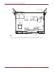


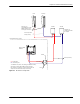

Table Of Contents

August 23, 2006 Revision 00b-DRAFT 31
Chapter 4: Installation Procedures
Install the Cards in the Chassis
The chassis contains slots for the following cards:
Sector controller – Front bottom slot, indicated by a red strip
Sector controller RTM – Rear bottom slot, indicated by a red strip
Modem card – Front top slot
Modem RTN – Rear top slot
Power supply – Front right slot
Figure 4.3 shows the locations of each card in the front of the chassis.
Figure 4.3
Card Layout
To insert the cards and power supply into the chassis
1 Ensure that there are no obstructions in the guide rails for each of the three slots and check the
backplane for bent pins.
If there are bent pins, the backplane is damaged and requires repair. Report any damaged equipment to
your SOMA Networks representative as soon as possible.
2 Use the following procedure to insert each of the following cards in order: chassis power supply, sector
controller RTM, modem RTM, sector controller, and modem card:
i Remove the card from its antistatic bag.
ii Set the ejector handles on the in the open position by turning the handles away from the center of
the front panel.
iii In the open position, the ejector handles are at an approximately 45° angle from the front panel.
iv Ensure that the mounting screws are withdrawn enough to allow for the insertion of the card.
v Orient the card so that the text on the front panel is right-side up. The guide pins should be located
to the right of the ejector handles.
vi Slide the card into the correct slot. Figure 4.3 shows the correct card layout. Use the guide rails to
ensure the connectors are aligned.
vii Apply sufficient pressure to fully mate the card by pressing on both ejector handles with equal force.
If present on the card, the guide pins should slide into the round holes located at the top and the
bottom of each slot on the right-hand side.
viii Lock the card in the slot by turning the ejector handles towards the center of the front panel.
ix In the lock position, the ejector handles are at a 90° angle from the front panel.
x Secure the card in the slot by installing the 2.5-mm mounting screws. Torque each screw to 0.4 N•m
(3 inch-pounds).
POWER
FAU L
T
Sector Controller
Modem Card
Power Supply