
Installation Manual
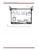
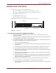

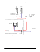

Table Of Contents

32 Revision 00b-DRAFT August 23, 2006
Macro Base Station Installation Procedures (NPM-2500)
Connect the PDP, Ethernet, and SERDES Cables
Table 4.2 shows the cabling for all the components in the base station.
To connect the cables
1 Connect the cables. See Table 4.2 for information about the origin and termination point of each cable.
2 Contact your SOMA Networks technical representative for information about your edge router cable
connections.
Cable From To
Power PDP (–48V, RTN GND) Chassis
PDP (–48V, RTN GND) Radio module (main)
PDP (–48V, RTN GND) Radio module (diversity)
PDP (–48V, RTN GND) Edge router
Ethernet Sector controller, EthA Edge router port 1
Sector controller, EthB Edge router port 2
SERDES Modem card RTM MAIN SERDES port on radio module (main)
Modem card RTM DIV SERDES port on radio module (diversity)
Table 4.2
Base Station Cabling