DSP 8-130 MKII SONAMP MULTI-CHANNEL POWER AMPLIFIER WITH ® I N S T R U C T I O N M A N UA L 06.14.
TABLE OF CONTENTS Safety 1 Introduction/Box Contents 3 Front Panel/Rear Panel 4 Amplifier Power Requirement Chart 5 Connections and Volume Level Controls 6 Protection Circuitry and LEDs 6 Rack Ear Installation and Shelf Mounting 6 Software V2 Network Connection Instructions Homepage 7 7 7 Basic Setup Page 7 Advanced Setup Page 8 General Settings Tab 8 In/Out Settings Tab 10 EQ Settings Tab 11 Specifications 14 Appendix A 15 Appendix B 16 Warranty 17
DSP 8-130 MKII SONAMP ® MULTI-CHANNEL POWER AMPLIFIER WITH INSTRUCTION MANUAL Important Safety Information • The amplifier has been exposed to rain. • The amplifier does not appear to operate normally or exhibits a marked change in performance. You should always follow these basic safety precautions when using your Sonamp DSP 8-130 MKII, to reduce the risk of fire, electric shock, and injury to persons: • The amplifier has been dropped, or the enclosure damaged. 1.
I N S T R U C T I O N S I M P O R TA N T E S C O N C E R N A N T L A S É C U R I T É 10. Protégez le câble d’alimentation secteur de telle manière qu’il ne puisse pas être écrasé ou pincé, particulièrement au niveau des prises, du passage dans des goulettes prévues à cet usage, ou à l’endroit où il sort de l’appareil. 1. Lisez soigneusement ces instructions. 2. Conservez-les en lieu sûr pour toute référence future. 3. Respectez scrupuleusement tous les avertissements de sécurité. 4.
Introduction Unpacking Thank you for purchasing the Sonance Sonamp DSP 8-130 MKII amplifier. When properly installed, this amplifier will give you many years of entertainment. To get the most out of your new amplifier, please read this manual thoroughly before you begin installation. Save the carton and polystyrene inserts for future safe transport in case the amplifier is moved or requires shipping for repair.
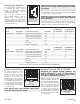
FIGURE 3: SONAMP DSP 8-130 MKII AMPLIFIER FRONT PANEL VIEW FIGURE 5: SONAMP DSP 8-130 MKII AMPLIFIER REAR PANEL VIEW Front Panel Rear Panel Power Switch The power switch turns the amplifier on and off. Line Inputs/Loop Outputs The DSP 8-130 MKII amplifier has four pair of LINE INPUTS and four pair of Loop OUTPUTS. When the Sonance logo on the power switch is lit bright white, the amplifier has power and is turned ON and ready to operate.
CAUTION Powering the 2-100 Amplifier LEVEL The Sonamp DSP 8-130 MKII features a removable IEC power connector (Figure 6). A 14-gauge EIA standard VOLTAGE TRIGGER 120-volt grounded power cable is IN OUT included with the amplifier. AUTO ON RISQUE DE CHOC ELECTRIQUE NE PAS OUVRIR AUDIO VOLTAGE Plug the female end of the power cable into the Power Connector on the amplifier’s rear panel and plug the male end directly into a grounded 15 amp or 20 amp wall outlet.
Source Connections DSP 8-130 MKII Protection Circuitry and LEDs On the left side of the rear panel are the left and right audio inputs for all eight channels. In addition to the audio inputs there are also loop outputs for each channel. The Sonamp amplifiers have a multi-stage protection system to prevent damage to your amplifier and speakers. See Appendix A.
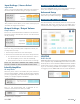
SONARC SOFTWARE NETWORK CONNECTION INSTRUCTIONS BASIC SETUP PAGE This page is for basic set up of EQ, Source and Volume. Equipment List Basic Setup 1. Computer or tablet To start, click on the Basic Setup button. 2. Network router with DHCP service enabled 3. Two RJ-45 cables (one when using wireless) Connecting to Your SONARC Homepage 1. The amplifier’s factory settings has DHCP set to ON. 2. Connect the amplifier to a network with a router.
Input Settings / Source Select ADVANCED SETUP PAGE Input Name This page in SONARC allows you to make advanced changes to the your amplifiers settings and configuration. This is a user entered field with a maximum of 15 characters. Use these fields to describe the type of input connected. Advanced Setup To start click on the Advanced Setup button from your MKII’s homepage. GENERAL SETTINGS TAB Input Source The Advanced Setup automatically starts out on the General Settings tab.
IP Address Auto On The second setting in the IP SETUP section is the IP address. When DHCP is ON the current IP address will be displayed. To change the IP address DHCP must be set to OFF. Select the Auto On method you would like to use with the blue pull down menu. During setup it is strongly recommended that you keep the Auto On method set to POWER BUTTON to prevent the amplifier from shutting off.
Sleep Mode Output Setup Sleep mode allows you to select how long the amplifier will stay active after the trigger method subsides. Output Name This is a user entered field with a maximum of 15 characters. Use these fields to describe the location of the speakers. Off Stereo / Mono When set in the OFF mode the channel will be on at all times. Use the OFF setting for audio signals like a doorbell or paging where audio must be reproduced immediately at any time.
Output Volume Test Signal Output Volume The SONARC software includes a built in pink noise generator. The pink noise signal can be used in conjunction with a real time analyzer to measure speakers. This is the main volume level control for each channel. When channels are placed in the same Output Group the levels will change simultaneously. Test Signal Select You have the option of pink noise or test signals fed into line level inputs.
Import Single Preset Parametric EQ 1. Import speaker preset to a location on your computer. This can be accomplished by saving a DSP preset downloaded from Sonance website. All Sonance DSP amplifier models feature a 10 band parametric EQ. Adjustments made to the EQ will be displayed on the Output Frequency Response graph. We strongly suggest not adjusting the EQ without proper measurement equipment. 2.
Tilt Control Limiter The tilt controls are very sophisticated bass and treble control. By selecting a start frequency and level you can ramp the bass and or treble up or down. The effect of the tilt control is visible in the Output Frequency Response graph. The limiter operates as a brick wall limit on the output of the amplifier. The limiter drop down menu has -3dB, -6dB and -12dB options.
SPECIFICATIONS SONAMP 8-130 MKII Number of Channels 8 (4 stereo pairs) Output Power - 8 ohms (Stereo) 130 Watts RMS per channel (all channels driven) Output Power - 4 ohms (Stereo) 145 Watts RMS per channel (all channels driven) Output Power - 8 ohms (Bridged) 300 Watts Frequency Response 5Hz – 50kHz (bandwidth limited) Total Harmonic Distortion 0.15% (1kHz, 8 ohms) 0.
APPENDIX A LED Indicator Explanation Dim White Power Button Amplifier is plugged in and in standby mode. Bright White Power Button Amplifier is active. Power Switch Blinking The amp is in ID Amp Mode (see page 9). Green LED Signal is present (>2.5mv) on channel. Blinking Green Signal is going above and below the active level or between songs. Blinking Red The channel is being overdriven. Solid Red The amp is in protection mode (see page 6).
APPENDIX B DSP 8-130 MKII Amplifier - Auto On / Sleep Mode Details AUTO ON SETTING SLEEP MODE OPTIONS TIME TO MUSIC ETHERNET AUDIO OFF Always On Always On AUDIO 15 MIN 6-8 seconds Always On AUDIO 3 HRS 6-8 seconds Always On AUTO ON SETTING SLEEP MODE OPTIONS TIME TO MUSIC ETHERNET AUDIO GREEN NONE 6-8 seconds Turns Off after 15 MIN without audio AUTO ON SETTING SLEEP MODE OPTIONS TIME TO MUSIC ETHERNET POWER BUTTON OFF Always On Always On POWER BUTTON 15 MIN 2-3 seconds
LIMITED TWO (2) YEAR WARRANTY Sonance warrants to the first end-user purchaser that this Sonamp-brand product (8-130 MKII Multi-Channel Power Amplifier), when purchased from an authorized Sonance Dealer/Distributor, will be free from defective workmanship and materials for the period stated below. Sonance will at its option and expense during the warranty period, either repair the defect or replace the Product with a new or remanufactured Product or a reasonable equivalent.