
User Manual


5
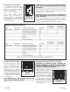
Powering the Amplifier
The Sonamp DSP 8-130 MKII features
a removable IEC power connector
(Figure 6). A 14-gauge EIA standard
120-volt grounded power cable is
included with the amplifier.
Each time the amplifier’s power
cord is initially plugged in and the
POWER switch is turned ON, all
channel outputs are disconnected
for approximately 9-12 seconds and all
PROTECTION LEDs will illuminate briefly
while the amp boots up.
IMPORTANT: DO NOT PLUG THE POWER CORD INTO THE WALL
OUTLET UNTIL ALL SYSTEM CONNECTIONS HAVE BEEN MADE
AND VERIFIED.
Plug the female end of the power cable into the Power Connector
on the amplifier’s rear panel and plug the male end directly into a
grounded 15 amp or 20 amp wall outlet.
IMPORTANT: DO NOT PLUG THE AMPLIFIER’S POWER CORD
INTO A CONVENIENCE OUTLET ON ANY OTHER AUDIO OR
VIDEO COMPONENT.
If the electrical service is subject to frequent sags, spikes, or
brownouts, a power conditioner designed for use with high fidelity
equipment should be employed to protect the amplifier.
Amplifiers Power Requirements:
15 AMP Breaker 20 AMP Breaker
Model Input Voltage Output Power (sinewave) Draw Watts Qty of Amplifiers Qty of Amplifiers
DSP 8-130 MKII 100-120V AC Full Power All Channels @8 ohms 1160 1 1
Full Power All Channels @4 ohms 1512 1 1
1/8 Power All Channels @8 ohms 181 7 10
1/8 Power All Channels @4 ohms 226 6 8
@ Idle 35
Sleep Mode 1.1
Voltage or Audio Green 0.45
13 AMP Breaker 20 AMP Breaker
Model Input Voltage Output Power (sinewave) Draw Watts Qty of Amplifiers Qty of Amplifiers
DSP 8-130 MKII 220-240V AC Full Power All Channels @8 ohms 1097 1 1
Full Power All Channels @4 ohms 1440 1 1
1/8 Power All Channels @8 ohms 182 7 10
1/8 Power All Channels @4 ohms 219 6 8
@ Idle 31
Sleep Mode 1.2
Voltage or Audio Green 0.48
FIGURE 7: SONAMP DSP 8-130 MKII MULTI-CHANNEL AMPLIFIER POWER REQUIREMENTS
IN
O
UT
1-L 1-R
LEVEL LEVEL
B
RIDGE
OFF ON
C
AUTION
RISK OF ELECTRIC SHOCK
D
O NOT OPEN
AVIS
RISQUE DE CHOC ELECTRIQUE
NE P
AS OUVRIR
S/N
T5AL / 250VAC
2-100
AC 100-120V ~ 60Hz
CAUTION
R
EPLACE FUSE ONLY WITH
S
AME TYPE AND RATING
ATTENTION
R
EMPLACER UNIQUEMENT AVEC LE
MEME TYP
E ET CALIBRE DU FUSIBLE
VOLTAGE TRIGGER
IN OUT
AUTO ON
OFF
1 - LEFT
1 - R
IGHT
BRIDGE
CLASS 2 WIRING
VOLTAGE
AUDIO
3-30 VOLTS
AC or DC
8 Ω MIN
AC 220-240V ~ 50Hz
52 watts
FIGURE 6: IEC POWER
CORD CONNECTION
Speaker Connections Bridging Channels DSP 8-130 MKII
FIGURE 8:
SPEAKER CONNECTORS
FIGURE 9: BRIDGING
CHANNELS
For the best sound you should
use premium speaker wire, that
complies with fire rating codes.
Be sure to check local codes
governing wire that may be
installed within walls or ceilings.
Sonamp amplifiers are stable with
any reputable brand of speaker wire
or cable. The Sonamp amplifiers
use speaker block connectors that
can accommodate up to 12 gauge
wire (see Figure 8).
IMPORTANT: THE MINIMUM SPEAKER IMPEDANCE FOR
BRIDGED OPERATION IS 8 OHMS. DO NOT OPERATE A
ZONE IN THE BRIDGED MODE INTO A SPEAKER THAT IS
LESS THAN 8 OHMS NOMINAL IMPEDANCE.
NOTE: ALWAYS CHECK LOCAL BUILDING CODES BEFORE
INSTALLING WIRE IN WALLS OR CEILINGS.
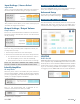
Bridging channels is accomplished
using the SONARC software. On
the second tab IN/OUT Settings, go
to the output setup area to bridge
mode and make your selections
with the drop down buttons (see
page 10). Connect the speaker’s
“+” lead to the left side of the
connector marked “+” (see figure 8).
Connect the speakers “-” lead to the
right side of the connector marked
“+” (see figure 9).
LEVEL LEVEL
B
RIDGE
OFF ON
MONOSTEREO
12-50
S/N
VOLTAGE TRIGGER
IN OUT
AUTO ON
OFF
IN
O
UT
IN
OUT
1-LEFT 1-RIGHT
LEVEL LEVEL
B
RIDGE
OFF ON
MONOSTEREO
LEVEL LEVEL
B
RIDGE
OFF ON
MONOSTEREO
LEVEL LEVEL
B
RIDGE
OFF ON
MONOSTEREO
LEVEL LEVEL
B
RIDGE
OFF ON
MONOSTEREO
LEVEL LEVEL
B
RIDGE
OFF ON
MONOSTEREO
2-LEFT 2-RIGHT 3-LEFT 3-RIGHT 4-LEFT 4-RIGHT 5-LEFT 5-RIGHT 6-LEFT 6-RIGHT
LOCAL
B
USS A
B
USS B
LOCAL
B
USS A
B
USS B
LOCAL
B
USS A
B
USS B
LOCAL
B
USS A
B
USS B
LOCAL
B
USS A
B
USS B
LOCAL
B
USS A
B
USS B
CAUTION
RISK OF ELECTRIC SHOCK
D
O NOT OPEN
AVIS
RISQUE DE CHOC ELECTRIQUE
NE P
AS OUVRIR
LEFT RIGHT LEFT RIGHT
BUSS INPUT A BUSS INPUT B
1 - LEFT
1 - RIGHT
BRIDGE
8 Ω MIN
CLASS 2 WIRING
T10AL / 250VAC
CAUTION
R
EPLACE FUSE ONLY WITH
SAME TYPE AND RATING
ATTENTION
REMPLACER UNIQUEMENT AVEC LE
M
EME TYPE ET CALIBRE DU FUSIBLE
2 - LEFT
2 - RIGHT
BRIDGE
CLASS 2 WIRING
3 - LEFT
3 - RIGHT
BRIDGE
CLASS 2 WIRING
5 - LEFT
5 - RIGHT
BRIDGE
CLASS 2 WIRING
6 - LEFT
6 - RIGHT
BRIDGE
CLASS 2 WIRING
4 - LEFT
4 - RIGHT
BRIDGE
CLASS 2 WIRING
VOLTAGE
AUDIO
3-30 VOLTS
AC or DC
8 Ω MIN 8 Ω MIN 8 Ω MIN 8 Ω MIN 8 Ω MIN
156 watts
AC 100-120V ~ 60Hz
AC 220-240V ~ 50Hz
LEVEL LEVEL
B
RIDGE
OFF ON
MONOSTEREO
12-50
S/N
VOLTAGE TRIGGER
IN OUT
AUTO ON
OFF
IN
O
UT
IN
OUT
1-LEFT 1-RIGHT
LEVEL LEVEL
B
RIDGE
OFF ON
MONOSTEREO
LEVEL LEVEL
B
RIDGE
OFF ON
MONOSTEREO
LEVEL LEVEL
B
RIDGE
OFF ON
MONOSTEREO
LEVEL LEVEL
B
RIDGE
OFF ON
MONOSTEREO
LEVEL LEVEL
B
RIDGE
OFF ON
MONOSTEREO
2-LEFT 2-RIGHT 3-LEFT 3-RIGHT 4-LEFT 4-RIGHT 5-LEFT 5-RIGHT 6-LEFT 6-RIGHT
LOCAL
B
USS A
B
USS B
LOCAL
B
USS A
B
USS B
LOCAL
B
USS A
B
USS B
LOCAL
B
USS A
B
USS B
LOCAL
B
USS A
B
USS B
LOCAL
B
USS A
B
USS B
CAUTION
RISK OF ELECTRIC SHOCK
D
O NOT OPEN
AVIS
RISQUE DE CHOC ELECTRIQUE
NE P
AS OUVRIR
LEFT RIGHT LEFT RIGHT
BUSS INPUT A BUSS INPUT B
1 - LEFT
1 - RIGHT
BRIDGE
8 Ω MIN
CLASS 2 WIRING
T10AL / 250VAC
CAUTION
R
EPLACE FUSE ONLY WITH
SAME TYPE AND RATING
ATTENTION
REMPLACER UNIQUEMENT AVEC LE
M
EME TYPE ET CALIBRE DU FUSIBLE
2 - LEFT
2 - RIGHT
BRIDGE
CLASS 2 WIRING
3 - LEFT
3 - RIGHT
BRIDGE
CLASS 2 WIRING
5 - LEFT
5 - RIGHT
BRIDGE
CLASS 2 WIRING
6 - LEFT
6 - RIGHT
BRIDGE
CLASS 2 WIRING
4 - LEFT
4 - RIGHT
BRIDGE
CLASS 2 WIRING
VOLTAGE
AUDIO
3-30 VOLTS
AC or DC
8 Ω MIN 8 Ω MIN 8 Ω MIN 8 Ω MIN 8 Ω MIN
156 watts
AC 100-120V ~ 60Hz
AC 220-240V ~ 50Hz