
User Manual


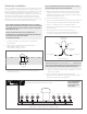
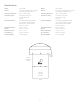


Figure 3: Connect
Subwoofer Installation
Sonance Landscape Series systems allow for speakers to be daisy
chained together. In a typical system with one zone of audio, run a
stereo or 4 conductor speaker wire from the amplier to the closest
speaker. Designate the rst speaker as either left or right and
connect the appropriate positive and negative wires to the speaker
terminals. Continue alternating the wires between the left and
right channels for each speaker, creating a daisy chain of stereo
satellites. The Subwoofer can be wired anywhere in the chain and
will receive either left or right speaker wires. See Figure 4.
4. Make the appropriate tap selection on the subwoofer before
lowering into the ground. To do so, remove the tap cap and
rotate the tap dial to the correct 70V/100V or 8 Ohm selection
and then rmly reinstall the cap.
5. Place the subwoofer into the ground.
6. Fine tune the enclosure depth as required so that the bottom of
the canopy will be 4” above the nished grade after backll.
7. Dig a 4” – 5” deep trench to run the speaker wires in.
8. Run the wire through the trench from your amplier to the rst
speaker location.
9. Connect the direct burial wire to each speaker wire,
connections should be made with either silicone lled wire
connectors or appropriate junction boxes. See Figure 3.
3. Prepare a ‘bed’ for the subwoofer that is reasonably free of
voids and large rocks.
A
C
B
A
C
B
Twist wires
together
Waterproof
Wire Nuts
From speaker To Amplifie
r
Positive
+
Negative
-
10. After all the speaker connections are completed, connect the
wires to your amplier.
11. Turn your amplier on and test the system with your
favorite music. If the speakers are operating properly, rell the
wire trench and enjoy your new speakers.
2
NOTE: SONANCE STRONGLY RECOMMENDS THE USE OF 14/4 DIRECT
BURIAL WIRE FOR DISTANCES UP TO 200 FEET AND 12/4 DIRECT BURIAL
FOR LONGER RUNS. KEEP WIRES AS SHORT AS POSSIBLE TO MINIMIZE
RESISTIVE WIRE LOSSES.
CAUTION: THE AMPLIFIER SHOULD NOT BE CONNECTED TO
AC POWER UNTIL ALL SPEAKER WIRE CONNECTIONS ARE COMPLETED.
HIGH POWER 70 VOLT AMPLIFIERS PRESENT
A SERIOUS SHOCK HAZARD.
1. Locate the subwoofer in an area that will not ood with
standing water.
2. Dig the hole using the following guide: See Figure 2.
LS12T SUB: A=4” B=16” C=17”
LS15T SUB: A=4” B=19” C=20”
Figure 2
NOTE: THE SUBWOOFER IS VERY HEAVY, ALWAYS TEAM LIFT. DO NOT
HOLD BY SPEAKER WIRE OR PLASTIC STRAIN RELIEF.
IMPORTANT: BE SURE NOT TO LET ANY STRAY ‘+’ & ‘–’ STRANDS TOUCH
EACH OTHER. TOUCHING STRANDS CAN CAUSE A SHORT-CIRCUIT THAT
COULD DAMAGE YOUR AMPLIFIER AND DEGRADE SOUND QUALITY.
Figure 4: 70V SLS Wiring Diagram
Conguration: 4 SATs:1 SUB or up to 8 SATs:1 SUB
Sonamp DSP 2-750 Amplifier
LS4T SATs/LS6T SATs & LS12T SUB or LS15T SUB
Expandable
LeftLeft RightRight LeftLeft RightRight
S/N
CAUTION
RISK OF ELECTRIC SHOCK
DO NOT OPEN
AVIS
RISQUE DE CHOC ELECTRIQUE
NE PAS OUVRIR
AC 100-120V ~ 60Hz
AC 220-240V ~ 50Hz
IR
CONTROL
TCP/IP
DEFAULT IP
1
92.168.1.50
IR
STATUS
IN
OUT
CAUTION
REPLACE FUSE ONLY WITH SAME
T
YPE AND RATING OF FUSE
A
TTENTION
REMPLACER UNIQUEMENT AVEC
LE MEME TYPE ET CALIBRE DU
FUSIBLE
T10AL / 250VAC
DSP2-750 MKII
+
1- LEFT
1- RIGHT
-
BRIDGE
4OHMSMIN
VOLTAGE TRIGGER
IN OUT
+
- -
+
3-30 volts AC /DC
IN
OUT
IN
OUT
1-L 1-R 2-L 2-R
+
-
+
-
NOTE: THE SUBWOOFER
CAN BE CONNECTED
AT ANY POINT IN THE
DAISY CHAIN.